
Everything You Should Have Known Long Ago About Your Model Aircraft's Avionics
A series of six workshops on the proper handling of electrical parameters in modern model aircraft flying.
The steps that are otherwise taken for granted in model building—such as weighing, measuring, or balancing, followed by comparison, refinement, or optimization—unfortunately often come to an abrupt end as soon as the model’s avionics are involved. “Too complicated,” is what you hear—often even from specialty retailers. Yet even in electrical engineering, measuring is nothing more than comparing. The only difference: we’re not talking about grams or kilograms, but about volts, amperes, and ohms—and the measuring device we use isn’t Grandma’s kitchen scale, but a digital multimeter. With this crash course, we want to explain in the simplest way possible
Avionics—a term derived from “aviation” (from the Latin *avis* = bird) and “electronics”—is a term used in aerospace engineering to refer to the totality of electrical and electronic equipment on board an aircraft, including flight instruments.
and provide a practical introduction to using a digital multimeter. Examples of simple and quick measurements from everyday model-building allow readers to immediately apply what they’ve learned. The reward is a better understanding of the model’s electrical system, resulting in fewer problems, better flight performance, and
Above all, more fun flying! Christoph and Franz Raible, www.innoflyer.ch
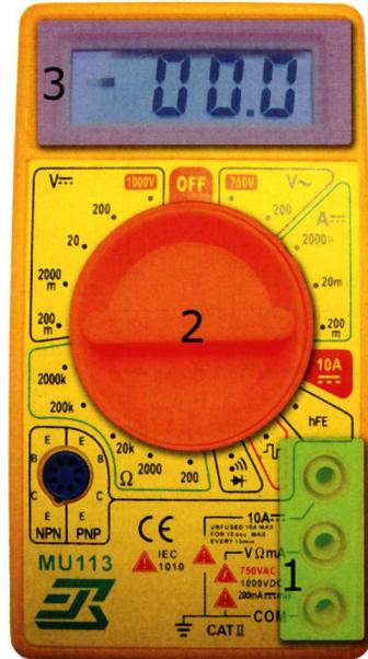
A digital multimeter (DMM for short) is a digital testing and measuring device used in electrical engineering to measure electric currents, voltages, and—depending on the model—various other parameters (resistance, temperature, continuity testing, etc.). The fact that this isn’t just a tool for professionals is evident from the simple fact that, at reputable model-making stores, you can purchase devices with more than enough features for as little as CHF 20.–. The countless types of DMMs available are all built in a very similar way. The DMM basically consists of a connector panel, a rotary switch for selecting the desired measurement function, and a display for showing the measurement result. Figure 1 shows these three components. In most cases, the connector panel has 3 jacks. One of these is used for all measurements (whether current, voltage—
(current or resistance) shared jack labeled “COM” or “REF.” A test lead must be connected here in every case. The second test lead is then connected—depending on the desired measurement—to either the terminal for measuring high currents (often labeled “10 A”) or the terminal for voltage measurement (usually labeled “V $Ω$ mA”), which is often also used for other functions such as resistance measurement or small currents (in the mA range). It is essential to use the correct terminal for the desired measurement parameter here. Otherwise, an accurate measurement is not possible!
The rotary switch is now used to select the desired measurement function. This distinguishes between the measured quantity (current, voltage, or resistance), the measurement range (e.g., 0–2 V or 0–20 V), and whether the quantity is DC or AC. In model building, we’re actually almost always dealing with DC voltage or DC current. Figure 2 shows the rotary switch with its typical selection options.
So, you now know the general structure of a DMM and
its adjustment options. Let’s try out a few practical experiments: We’ll start by measuring voltages. A frequently discussed topic is balancing LiPo cells. But how good is my balancer, really? Are my batteries truly balanced, and are all the cell voltages in the battery pack the same? This can be quickly checked with the DMM.
To do this, connect the test probes to the “COM” jack and the “V $Ω$ mA” jack on the DMM. Since we want to measure a DC voltage in the range of 2.5 V–4.2 V (the voltage range of a LiPo cell), use the rotary switch to select the 20 V DC measurement function. Figure 3 shows these settings. Using the test probes, you can now measure the cell voltage at the balancing connector of the battery pack by always measuring between two adjacent contacts. Do this for all cells and compare the measured voltages. If you measure negative voltages, you have simply swapped the test probes. You can either ignore this (knowing that the voltage cannot be negative in this case) or swap the test probes on the two contacts (reverse the polarity). Afterward, the voltage will be displayed as positive—
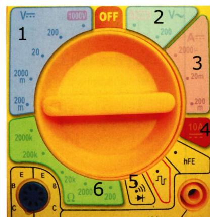
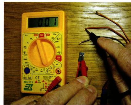
Figure 4 shows the measurement at the balancing connector. Be careful not to short-circuit the two test probes when working with delicate balancing connectors. Furthermore, with this DMM setting, you can also determine the total voltage of the battery, for example, by measuring directly at the battery’s positive and negative terminals. Not sure whether your ESC has a 5-V or 6-V BEC? No problem—quickly measure it this way at the servo connector
(usually the red and black wires). These are just three examples of how and where voltages in model avionics can be checked very quickly. There are countless other useful measurements. We’re sure you already have your own ideas about where you’d like to take some measurements. Go ahead and do it!
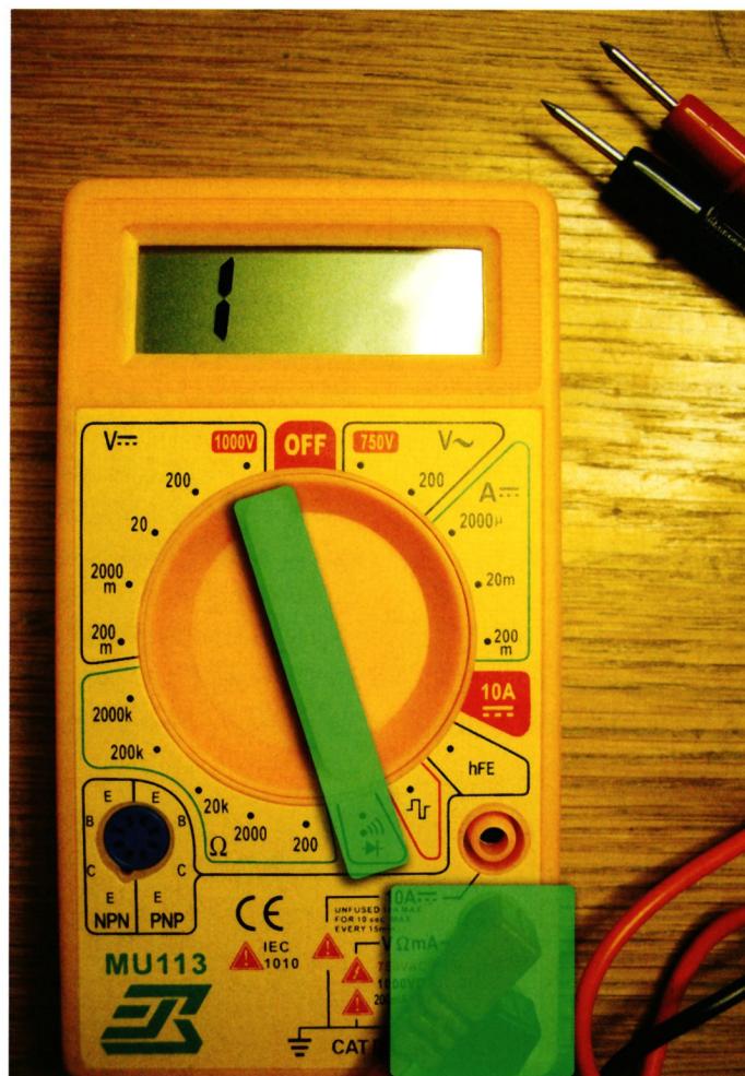
For us model builders, the DMM has another extremely practical function: the continuity test. This allows you to check whether a cable or connector is making proper contact. To do this, configure the DMM as shown in Figure 5. As soon as there is electrical contact between the two test probes, a beep sounds (test it
by directly connecting the two test probes). This way, you can, for example, check a servo extension before installing it in the wing. This helps you detect broken wires, poor connections, and other issues. Figure 6 shows the continuity test for a servo extension. Perform the continuity test only on parts that are not live (always turn off the device under test or disconnect it from the power source first).
When we introduced the DMM, we saw that the device can also be used to measure current. Unfortunately, common DMMs very often only have current measurement ranges up to 10 A. This is insufficient for model building, since in many cases we deal with higher currents in the—
drive systems. Furthermore, inexpensive DMMs (< CHF 1,000) usually lack the technical capabilities required to accurately measure the currents switched by modern brushless DC controllers. However, using simple tools, it is still possible to take precise current measurements in the drive system with a DMM. More on this in the next issue.
All the materials needed to replicate this workshop at home in your workshop are available at a good model-making specialty store or at www.innoflyer.ch
To accompany this 6-part workshop series, you'll find a blog at www.innoflyer.ch where the topics covered in the magazine are explored and discussed in greater depth.


TEAM MANAGER "THIS" BOSSHARD
 Rodito Nussbaumer

SUMMER FUN 2026 AT MG USTER
Martin Wunderli
52. 2026 ALPS CUP
 Emil Giezendanner

ATOM, THE NEW DOUBLE-DECKER FROM CPLR
 Matthias Bosshard

INSIGHTS INTO THE HISTORY OF SEAPLANES

34th HAHNENMOOS ALPINE MODEL AIRPLANE CAMP
Res Dauwalder
CORSAIR F4U – A WARBIRD WITH A MEMORABLE LOOK
Jürgen Rosenberger, Jürgen Prinz
SMALL, MODEL-LIKE SAILBOATS
Res Dauwalder
F3A EUROPEAN CHAMPIONSHIPS IN ST-MACAIRE, FRANCE
Matthias Bosshard
What's New at Leomotion.com

HORIZON HOBBY/LEMACO NEWS: MICRO OV-10 BRONCO 645 MM BY E-FLITE

PRIDE AND GOOD IDEAS
 Markus Nussbaumer

News from HEBU

BY YOUTH, FOR YOUTH
Lorena Betschen
YOU KNOW WHAT I MEAN? 125 YEARS OF THE SWISS AERO CLUB
Emil Giezendanner
TRY-OUT DAY AT MFV WETTINGEN
Urs Keller
FREE FLIGHT IN THE MIDDLE OF SUMMER
Urs Muntwyler
THE PC-21 STORY
Emil Giezendanner
TWIN TOWN PARTNERSHIP
Wolfgang Voeller
EURO CONTEST GLIDER ACRO TOUR AUSTRIA 2026

WELCOME, NEW MEMBER!
Andrea Bolliger
COUPE DES ALPES – OBSERVE AND LEARN
Rodito Nussbaumer
NEWS FROM HEBU
 Julia Bucher

FROM 0 TO 100
Markus Nussbaumer
MEMORIES
Wolfgang Völler
NOS REGION – A HUB FOR ELECTRIC AVIATION
Emil Giezendanner
Have you almost forgotten about aircraft that take off and land vertically?
Emil Giezendanner
70 YEARS OF THE NIDWALDEN MODEL AIRPLANE CLUB
Martin Barmettler