
"Soaring Albatros," a modern, large wooden sailboat
After many years away from active model gliding, I was struck last fall by the idea of designing and building a high-performance large glider myself. My goal was to create a glider that was easy to fly, had good thermal performance, and looked beautiful in flight.

| Wingspan: | 5.2 m |
| Fuselage length: | 2.05 m |
| Weight: | 6.9 kg |
| Wing loading: | approx. 56 g/dm² |
From the initial idea to the assembly of all wooden parts, the PC—along with powerful software—serves as an important tool. The flowchart below illustrates the relationships involved.
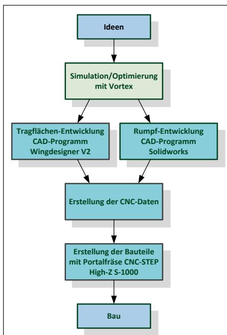
By using the Vortex simulation program, the desired characteristics of a model aircraft can be determined and optimized in advance. Based on positive practical experience, I decided to use the HQW-3013 airfoil for the inner wing throughout up to $\frac{2}{3}$ of the wingspan and to transition from HQW-3013 to HQW-3014 on the outer wing. Additional dihedral on the outer wing set to $-1$ degree. The proven symmetrical NACA0009 profile is used for the elevator and rudder. Contributing to stable flight behavior is a double-V shape on each wing half, with 2 degrees on the inner wing and 6 degrees on the outer wing.
The CAD design of the wings was created using “Wing Designer V2.” On the wing, wide flaps and ailerons (25% of the wing depth) ensure effective control. The outer third of the wing can be removed for transport. The elevator is designed as a pendulum elevator, so the EWD self-adjusts during flight when the center of gravity is correctly positioned. All surfaces are constructed using traditional balsa/plywood construction. They are covered with opaque white Oratex film, and the translucent sections are covered with blue Oracover.
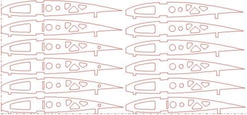
Aerodynamically well-designed winglets (HQW-3014 stretched to NACA0009!) effectively dissipate the wing tip vortices. Based purely on calculations (vortex dynamics), the winglets result in a slight improvement in the glide ratio of about 3%.
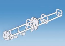
All parts of the fuselage were designed using the SolidWorks CAD program and visualized and inspected prior to assembly. I also built the fuselage using traditional woodworking techniques. The use of aircraft plywood with countless cutouts to reduce weight results in a stable airframe. The entire fuselage was then covered with 4 mm balsa wood and sanded. I reinforced the front underside of the fuselage with fiberglass cloth and attached a beech wood skid. I hardened the balsa surface with PU parquet varnish and then covered it with Oratex.
Using my portal milling machine, I was able to mill all the parts I designed efficiently and with precision.
The “Soaring Albatros” can be flown either as a pure glider (with a removable nose section featuring a tow hook and servo) or powered by a 1,200-watt outrunner electric motor (Eflite Power 60). Battery: 5-cell LiPo, 5,000 mAh.
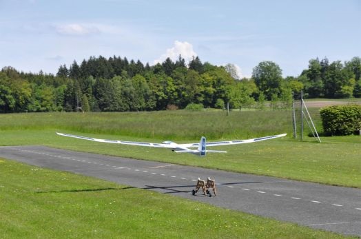
The maiden flight of the “Soaring Albatros” took place on June 5, 2013, at the model airfield in Müswangen, LU. The center of gravity and EWD were adjusted according to the Vortex program. The Butterfly settings were as usual (flaps at 60°, ailerons up 10°), along with aileron differential. The launch from the cart worked perfectly on the first try. Experienced pilot Hans Baumann attested that the motor glider exhibited flawless flight behavior. The only subsequent adjustment required during Butterfly operation was to add a corresponding amount of elevator input, to prevent a slight nose-up pitch. Since then, the motor glider has completed countless flights. It impresses with its majestic flight profile as well as its excellent gliding performance. The partially transparent wings offer a wonderful, nostalgic-looking sight. In the event of a stall, there is no tendency to tip over the wings, but only a slight pitch and a return to stable flight—just as it should be. Thanks to its double V-shape, it can fly very tight turns in thermals. “Low pass” flybys at higher speeds are also very impressive, accompanied by a clearly audible whoosh.
The installation of a telemetry system is already underway. Among other things, I hope this will allow me to roughly verify the glide ratio of 1:29 calculated by Vortex. Although the model fulfills its intended purpose and is a lot of fun to fly, I’m already thinking about a successor. Keywords: CAD design entirely in SolidWorks, wings each made from a single piece, a fuselage with a slightly more elegant shape.
www.solidworks.com
SolidWorks
CAD software www.laumat.ch
CAD software Wing Designer V2
frankranis@gmx.de
Frank Ranis, Vortex simulation program
www.cnc-step.de
Manufacturer of the gantry milling machine used:
www.mgmueswangen.ch
Müswangen Model Aircraft Club,
photos from January 23, 2013, and June 27, 2013


News from HEBU

TEAM MANAGER "THIS" BOSSHARD
 Rodito Nussbaumer

SUMMER FUN 2026 AT MG USTER
Martin Wunderli
BY YOUTH, FOR YOUTH
Lorena Betschen
SMALL, MODEL-LIKE SAILBOATS
Res Dauwalder
TRY-OUT DAY AT MFV WETTINGEN
Urs Keller
What's New at Leomotion.com

52. 2026 ALPS CUP
 Emil Giezendanner

ATOM, THE NEW DOUBLE-DECKER FROM CPLR
 Matthias Bosshard

INSIGHTS INTO THE HISTORY OF SEAPLANES

YOU KNOW WHAT I MEAN? 125 YEARS OF THE SWISS AERO CLUB
Emil Giezendanner
34th HAHNENMOOS ALPINE MODEL AIRPLANE CAMP
Res Dauwalder
CORSAIR F4U – A WARBIRD WITH A MEMORABLE LOOK
Jürgen Rosenberger, Jürgen Prinz
F3A EUROPEAN CHAMPIONSHIPS IN ST-MACAIRE, FRANCE
Matthias Bosshard
HORIZON HOBBY/LEMACO NEWS: MICRO OV-10 BRONCO 645 MM BY E-FLITE

PRIDE AND GOOD IDEAS
 Markus Nussbaumer

EURO CONTEST GLIDER ACRO TOUR AUSTRIA 2026

FREE FLIGHT IN THE MIDDLE OF SUMMER
Urs Muntwyler
THE PC-21 STORY
Emil Giezendanner
TWIN TOWN PARTNERSHIP
Wolfgang Voeller
WELCOME, NEW MEMBER!
Andrea Bolliger
COUPE DES ALPES – OBSERVE AND LEARN
Rodito Nussbaumer
NEWS FROM HEBU
 Julia Bucher

FROM 0 TO 100
Markus Nussbaumer
MEMORIES
Wolfgang Völler
NOS REGION – A HUB FOR ELECTRIC AVIATION
Emil Giezendanner
Have you almost forgotten about aircraft that take off and land vertically?
Emil Giezendanner
70 YEARS OF THE NIDWALDEN MODEL AIRPLANE CLUB
Martin Barmettler