
All My Little Ducks
No, COVID-19 really isn’t to blame for everything. But a lockdown like this can easily become a breeding ground for projects that had previously fallen by the wayside due to a supposed lack of time. When you can’t fly and there’s a general lack of outdoor recreation, construction projects come to the forefront that had previously been simmering in the back of your mind. In my case—admittedly long before the pandemic—these were a few ducks, or to put it more elegantly, “canards,” flying machines with which the Wright brothers once pioneered powered flight, but which then—such is the way of the world—somehow ended up as wallflowers.
Ducks in aircraft design, as is likely well known, have the elevator at the front. This means the control surfaces move in exactly the opposite direction than on “normal” airplanes. And, to add to the confusion, they usually have the propeller all the way at the rear. In short: They fly the wrong way around. This causes some confusion, occasionally even among model airplane enthusiasts, who have always been considered innovative and open to unusual ideas. But it seems that mass-produced foam models and ready-to-fly kits from Eastern Europe and Southeast Asia haven’t been without their normative influence: Why bother learning how to milk a cow when fresh milk is right there on the supermarket shelf? Occasional advice from clubmates to finally treat yourself to something “decent” instead of that “crazy stuff” is inevitable. If you’d like to keep reading here, you might want to be able to live with that kind of thing.
It’s not as if there were no precedents for canards in the passenger-carrying sector. To name just a few, there’s the well-known “SPEED Canard” from Gyroflug, which was the first sport aircraft in a canard configuration worldwide to receive type certification. Also widely known are the designs by American Bert Rutan, realized as the “Varieze” and “Long EZ.” Enthusiasts of particularly aesthetically pleasing aircraft models may recall the “Starship,” a twin-engine propeller aircraft from Beech Aircraft. According to Wikipedia, this canard aircraft is among the most advanced in civil aviation. In the field of research aircraft, the designers of the “Voyager” relied on the canard configuration.
Even the military aviation sector experimented with canard configurations under the pressure of World War II. The most interesting example is likely the “Shinden,” developed in Japan, which, however, arrived too late in 1945 to change the course of world history. Among later projects, the Grumman X-29, with its forward-swept main wing, stands out in particular.
In modern military jets with a delta configuration, the canard wing is once again gaining prominence. Here, however, it primarily serves a supporting function. It is designed to resolve the lift problem specific to delta wings, where, when the elevator is deflected upward, the chord line shifts toward a smaller angle of attack. Early examples include the “Saab Viggen,” the legendary “XB-70 Valkyrie,” and—still in service today—the “EFA Eurofighter.”
As for the initial infection with the duck virus, it had already occurred more than
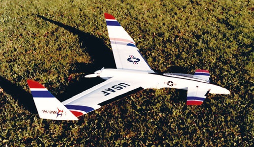
More than 20 years ago, I came across an American wooden model kit called “Tristar” (distributed by Hölllein). It was a functional model with a futuristic look, featuring a highly swept wing with winglets on the outer edges and a propeller at the rear. The model was originally designed for small internal combustion engines—not exactly a thing of beauty, but it flew fantastically and, toward the end of its service life—shortly after the turn of the millennium—served as a test platform for the first LRK engines. At some point, I replaced the utilitarian table leg that held the wing and tail together with something voluminous, resembling a round-fuselage design. Inside the tube, a 90-mm impeller was now free to run wild, drawing in air from the underside much like an F-16. It gave this Tristar knockoff a more authentic sound and a magnificent flight speed. Unfortunately, the strength of the wing—which was already quite old at the time and had thin skin—couldn’t withstand the strain over the long term. Well, it was worth a try!
The surprisingly well-preserved remains were fitted with a new, this time non-swept wing with winglets at the aileron roots, as well as a new foil design. This model, too, flew right away after a skillful hand launch and became the model for several subsequent versions—
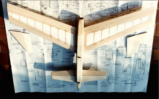
Airframes, all of which were designed according to a very similar construction principle: high-wing aircraft with trapezoidal wings, featuring a wingspan of 114 cm, a profile depth of 25 cm at the center, 15 cm at the wingtip, and a profile similar to the RG 15. A compact air duct with an impeller assembly located roughly halfway down (center of gravity!) and a slightly conical nozzle tube that tapers to approximately 85% of the inlet area. Due to the compact design, a lateral control surface was omitted. The duck wing was initially unprofiled. Later, thin, symmetrical profiles were used, such as those commonly found on glider tail units. The EWD was approximately 2 degrees. To aid takeoff, later versions were equipped with a hook for a rubber slingshot, allowing them to operate independently of specialized launch personnel. The only nuisance during landing was that the belly-mounted air intake refused to reliably give up its penchant for digging into the ground. A fiberglass landing spur added to the front later on remedied the problem.
Takeoffs and landings take on a special appeal—in more ways than one—when they look just like those of a real airplane. I had in mind a ground-launchable project modeled after a real aircraft. I chose the Kyushu J7W1 “Shinden.” Well, it’s so compli-
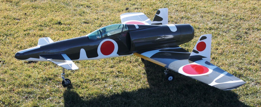
You don’t necessarily have to start with the details. But, I’ll let you in on a secret: it was exciting and inspiring. Even the original had seen the light of day in Japan under adverse circumstances. Designed to intercept incoming American bomber formations, Japanese engineers struggled primarily with material shortages toward the end of World War II. The powerplant—an 18-cylinder double-row radial engine from Mitsubishi—had to drive a pressure propeller. This came at the cost of an exceptionally long-legged landing gear, so that the 6-bladed propeller—located behind the pivot point—would have the necessary ground clearance to take off without scraping the ground
. The ultimate goal of the development was therefore the installation of a 900-kp jet engine, but this did not come to pass in 1945 after Hiroshima. Some time ago, I’d come across a report in a Japanese model-building magazine that described this project—which was incredibly advanced for its time—in great detail. One tiny flaw: it was all in Japanese! However, the three-view drawing—which unfolded to A3 size—seemed usable, as at least some of the numerical data was legible. These served as the construction template for the Shinden model project with a 154-cm wingspan. The airfoil profile could be estimated as a thinly compressed Clark-Y, with its chord line parallel to the
It ran along the longitudinal axis. A flat plate was intended to serve as the leading edge; since numbers without legible labels can sometimes be misleading, I set its angle of attack to 3 degrees.
It later turned out that this was too much, which is why the Shinden took to the air with its elevator set to a slightly negative (i.e., upward!) angle for the rest of its life.
But that didn’t detract from the sense of accomplishment at first. Powered by a 90-mm impeller (6s), the model flew practically right away and exhibited excellent flight characteristics, even if they took some getting used to at first. After a somewhat turbulent maiden flight—which was corrected by shifting the center of gravity forward—it was primarily the unfamiliar flight behavior that took some getting used to. In this original version, the takeoff process also tended to get out of control. The nose wheel, which was initially positioned too far forward,
. Due to the long lever arm between the nose wheel and the center of gravity (which is located just in front of the wing leading edge), the model tended to bounce slightly on the grass runway, causing it to veer off course. It was then moved closer to the center of gravity—that is, further back—as planned, and now inevitably rolls forward. The control response around the lateral axis also seemed slightly in need of improvement, which was likely due to the lack of a airfoil profile on the duck wing. One could get used to all of that—but as I said before: The lesson
“Shinden” was an encouraging success, as well as interesting and instructive.
I'll admit it: I don't really like building wings. That’s why the newer Canard creations are, strictly speaking, conversion or recycling projects. At the very least, they use the wings from conventional models that have become either too boring in their original form or partially damaged due to careless use.
It all started with a modified 1.4-meter Funtana (formerly distributed by Staufenbiel)—a stroke of luck—
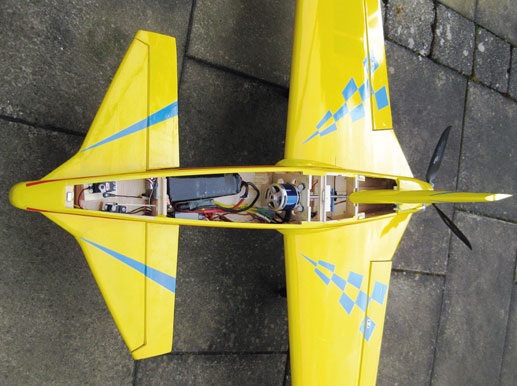
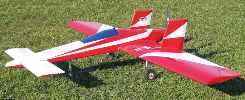
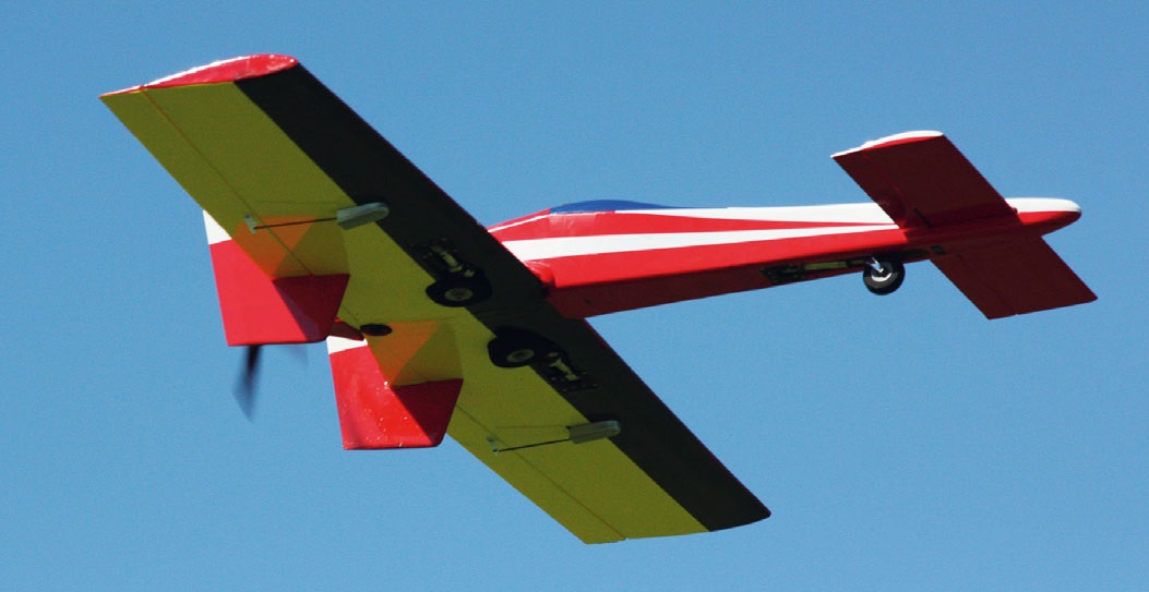
In this case, because in addition to the wings, parts of the horizontal and vertical stabilizers were also “reusable.” Nevertheless, creativity was required to design a new fuselage that would combine these three aerodynamically effective elements into a flying canard. Incidentally, 3-mm poplar plywood has proven to be ideal for building new fuselages like this; it can even handle a few lightening holes in non-critical areas. After a rough determination of the center of gravity, it became clear that the motor would have to vacate its spot on the comfortable back seat and be moved into the fuselage—
Since it had to be moved to the center, we didn’t want to have to stuff thick lead weights into the nose. The outrunner now drove the tail propeller via a 6-mm hollow steel shaft. A three-bladed propeller was chosen simply because the diameter couldn’t be too large here—otherwise, there would be a risk of the blade tips touching the ground during takeoff. This is probably an unusual feature for a model airplane, but, as will be discussed later, it doesn’t seem to impair flight performance.
The reverse-flight model, rolling on a fixed landing gear, was the pride and joy of its proud parents from the very beginning. Without any fuss, it took off after just a few meters, climbed powerfully, and let itself be maneuvered into just about any position that the “organ-donor” Funtana had already mastered. No, there was nothing to
, except that the model pilot has to get used to the flight characteristics again—especially when, as here, the nose wing and main wing are very close together (a “short-coupled” Duck). Yes, and the chattering could get a bit loud, as always when the propeller whirs so close behind the vertical stabilizer.
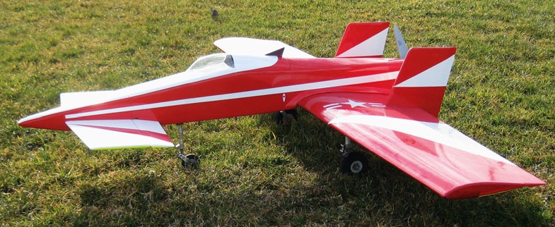
The next project was to be built on a similar basis but with retractable landing gear. Again, a mid-engine design with a 3-blade push propeller (11" x 8"), this time—since it was available—a rectangular wing with a 132 cm wingspan. The now-rigid vertical stabilizers were moved outward—primarily for noise reduction—all the way to the aileron attachment points. For the canard wing, I went with a flat panel again—it had worked so far. The distance between—
Duck-wing models always have a lifting tailplane, since it is located ahead of the center of gravity. Therefore, when determining the wing loading, one can safely add the areas of both wings together. In practice, however, this clearly positive aspect is offset by the fact that two small wings are aerodynamically less efficient than one large one (twice the induced drag). In addition, the rear wing can be affected by the wake from the front wing. It is therefore advantageous to position the canard wing relatively high, though this is naturally subject to design constraints. A high-mounted canard also offers the advantage that the section of the fuselage above the canard becomes relatively flat. This prevents one-sided shadowing of the canard should a glide flight ever occur.
Motors (we have no experience with sail canards) undoubtedly benefit from pressure propulsion. Small propellers achieve better efficiency this way, which is particularly advantageous for fast models. Incidentally, you don’t need special pusher propellers, since you can simply reverse the propellers—that is, mount them on the shaft from the front. Furthermore, airflow does not strike the models’ vertical stabilizers, so they are not subjected to asymmetrical forces; therefore, there is no need to worry about the propeller’s lateral pull. The propeller pitch should be such that the imaginary extension of the motor shaft passes through the center of gravity in the Z-direction (along the vertical axis). This can be easily determined by supporting the fuselage on the side with your finger. Of course, the center of gravity in the X-direction (see below) should be known beforehand. Since this is usually located near the leading edge of the wing, care must be taken to ensure a sufficiently large rudder surface, as the corresponding lever arm tends to be rather short. Winglets are considered a proven rudder design.
The center of gravity’s position also affects the landing gear configuration. During takeoff, the pivot point shifts from the wheel axis to the center of gravity. If the main landing gear is positioned too far behind the center of gravity, higher lift forces are required for takeoff due to the excessively long lever arm. Unused surfaces on models that originally had a tricycle landing gear are therefore less suitable. A nose landing gear positioned too far forward is also problematic, as it tends to bounce on rough grass runways, causing the model to lose its direction.
It is well known that when “ducks” fly in a stall, the airflow over the leading edge of the wing breaks off first. The model then briefly dips its nose—if it has one—into lower air layers to regain speed. In flight, it looks as if
Continue the maneuver by nodding the head. However, if the aircraft is flying too low, this can only be done once.
In the literature on duck-wing designs, an EWD of 3 to 6 degrees is often recommended—which, in my experience, is too high. This may apply to very slow-flying models. For models of the type described here, angles of 1.5 to 2 degrees have proven to be appropriate. Even though unprofiled board-type tail surfaces have worked in some cases, overall, the results with lifting-profile tail surfaces are clearly better.
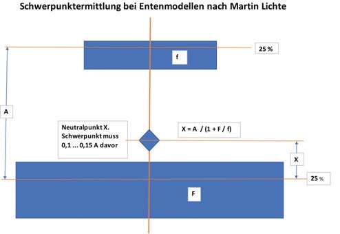
Yes, and then there’s the crux of the matter with the center of gravity in the X-axis or longitudinal direction. Even a rough calculation isn’t as straightforward as with a conventional tailplane configuration, where you simply hold your finger at one-third of the wing depth.
There is a graphical calculation program (see attachment) that is easy to use for simple wing geometries—such as the “Square” example.
Otherwise, computer programs like Dieter Schall’s “ENTEX” can help. Their reliability depends entirely on the accuracy of the model dimensions entered. This can become somewhat tricky for models with, for example, elliptical surfaces, because you then have to approximate the geometry using rectangular or trapezoidal shapes. In practice, it is strongly recommended to add a safety margin of one to two fingers’ width toward the front. Tail-heavy “ducks” can behave extremely erratically. In the worst case, the model may go into a spin. The center of gravity is too far forward if you have to rely heavily on the elevator to stabilize the model during turns. This can then be gradually corrected by shifting the center of gravity backward.
to pull the oars, which certainly had the desired effect. Nose up, take off—it’s working! But the joy was short-lived and premature, because at a height of barely 2 meters, the beak of the springless creature snapped downward as if struck by a ghostly hand, only to be stuck in the dirt a fraction of a second later. What was that? Well, the airflow probably stalled at the duck’s wing (see box). Nevertheless, the damage was localized; my duck got a second chance, but this time with a tail unit featuring a Clark-Y profile. And lo and behold, there was no more hammering on the nose. “Square” climbed perfectly to altitude and was as controllable as the “Graupner Taxi,” once beloved in beginner circles. Even
the landings went off without a hitch.
It soon became clear that, after this nose job, the “Duck” not only flew superbly but was also capable of a decidedly brisk pace. Powered by a Pichler BOOST 50 (600 kv) outrunner motor and a 6S battery with 3800 mAh, it speeds off in any direction when
necessary, and accelerates vertically into the air. A fun little aircraft where, after extensive flying, only one question seems to remain: When will the battery finally run out? Quite obviously, the tail-mounted propulsion system works very efficiently even with the three-blade propeller. The only explanation for this is that the propeller blast doesn’t interfere with the fuselage here, but flows freely backward
Experimental flight remains exciting even in times when the model aviator, eager to maintain his reputation, picks up his 9-meter glider “Klapptriebwerk” —GPS return aid included—from a high-end workshop, usually in exchange for a low five-figure sum, or, if funds are more limited, from the
A plug-and-play version that comes in a four-color, but printed, cardboard box. While forging your own path to the summit of satisfaction may not always be the easiest—
, but they’re certainly more interesting than well-trodden paths with a professionally pre-installed safety rope. And, to try something on my own again,
you don’t really need a new lockdown. ■
Photos: Ludwig Retzbach and Philipp Mattle


News from HEBU

TEAM MANAGER "THIS" BOSSHARD
 Rodito Nussbaumer

YOU KNOW WHAT I MEAN? 125 YEARS OF THE SWISS AERO CLUB
 Emil Giezendanner

F3A EUROPEAN CHAMPIONSHIPS IN ST-MACAIRE, FRANCE
 Matthias Bosshard

52. 2026 ALPS CUP
Emil Giezendanner
PRIDE AND GOOD IDEAS
 Markus Nussbaumer

ATOM, THE NEW DOUBLE-DECKER FROM CPLR
Matthias Bosshard
CORSAIR F4U – A WARBIRD WITH A MEMORABLE LOOK
Jürgen Rosenberger, Jürgen Prinz
SUMMER FUN 2026 AT MG USTER
Martin Wunderli
TRY-OUT DAY AT MFV WETTINGEN
Urs Keller
TWIN TOWN PARTNERSHIP
Wolfgang Voeller
BY YOUTH, FOR YOUTH
Lorena Betschen
SMALL, MODEL-LIKE SAILBOATS
Res Dauwalder
What's New at Leomotion.com

HORIZON HOBBY/LEMACO NEWS: MICRO OV-10 BRONCO 645 MM BY E-FLITE

COUPE DES ALPES – OBSERVE AND LEARN
Rodito Nussbaumer
EURO CONTEST GLIDER ACRO TOUR AUSTRIA 2026

INSIGHTS INTO THE HISTORY OF SEAPLANES

34th HAHNENMOOS ALPINE MODEL AIRPLANE CAMP
Res Dauwalder
WELCOME, NEW MEMBER!
Andrea Bolliger
FREE FLIGHT IN THE MIDDLE OF SUMMER
Urs Muntwyler
THE PC-21 STORY
Emil Giezendanner
NEWS FROM HEBU
 Julia Bucher

FROM 0 TO 100
Markus Nussbaumer
MEMORIES
Wolfgang Völler
NOS REGION – A HUB FOR ELECTRIC AVIATION
Emil Giezendanner
Have you almost forgotten about aircraft that take off and land vertically?
Emil Giezendanner
DO YOU KNOW WHAT I MEAN IN THE LAND OF SMILES?
Emil Giezendanner