
Chopper Speed Controller for 20 A
The speed controller, for which these assembly instructions are provided, offers the following advantages:
- Output voltage adjustable from negative values up to full battery voltage.
- Power loss is negligible thanks to the use of a special output stage and a speed relay.
- Immunity to interference is maximized, even at long ranges, thanks to galvanic isolation between the receiver and power circuits.
- Low current draw from the receiver battery. For this reason and the one mentioned above, the receiver is not powered by the power battery.
- The chopper frequency is 440 Hz. This results in exceptionally smooth motor operation and better efficiency than with the standard 50 Hz.
- If the transmitter signal is lost (e.g., out of range) or the receiver is turned off, the output voltage is immediately suppressed, meaning the motor does not briefly turn on when the transmitter or receiver is turned on or off.
- Low weight thanks to the use of state-of-the-art components. This makes it suitable for use in all areas of electric model building.
- Versions are available for positive and negative input pulses (including for Varioprop), for normal forward/reverse operation (or propeller stop for folding propellers), or for electric cars with a lossless brake and a fixed reverse speed.
To make it possible even for non-experts to build this controller—and because this type of controller is new—this description is very detailed.
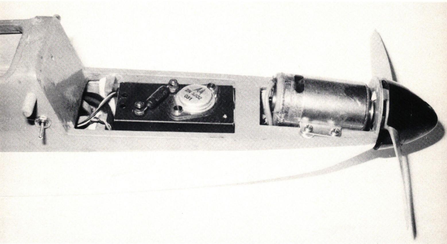
Installation in the ELEKTRO-FLY Jumbo 550, 10 cells: $I_{max} = 15\text{ A}$ . The H11 is housed in a TO3 package here. R35 was mounted outside the enclosure to allow it to be adjusted for different battery voltages.
(Fig. 1)
The device is essentially divided into pulse, control, and power sections.
The pulse section consists of a pulse-length-to-voltage converter, pulse monitoring circuit, triangle wave generator, and an adder. The pulse-length-to-voltage converter outputs a voltage Up that corresponds to the input pulse length or the position of the control knob. The pulse monitor activates the output stage only when an input pulse is present. The triangle wave generator provides the chopper frequency of 440 Hz, which is mixed with Up in the summing stage to produce the voltage Uc. Uc is thus a triangular voltage whose average value changes with the joystick position (Fig. 2).
The control section consists of a comparator with a voltage divider, the relays, and the optocouplers for driving the power section and controlling the base current of the main power transistor. Comparators 1–4 coordinate the switching of the relays and optocouplers—and, respectively, the corresponding power transistors—depending on Up and Uc.
| Output current | Continuous: | 20 A |
| Peak: | 40 A (0.1 s) | |
| Output voltage | (% battery): | -80% - 100% |
| for the Car model: | -80%, 0–100% | |
| Battery voltage: | 6 V - 27 V | |
| Receiver voltage: | 4 V - 6 V | |
| Power consumption | Standby: | 5 mA |
| Max.: | 55 mA | |
| Mechanical | Weight: | 95 g (without cable) 60 g (without housing) |
| Dimensions: | 70 × 32 × 30 mm |
The power amplifier is designed as a so-called H-bridge circuit, with one branch consisting of the two power transistors and the other of relay K1. This has the advantage that only single-pole relays are needed (in speed mode, there are thus only two relay contacts between the motor and the power battery).
If the control stick on the transmitter is in the neutral position, the voltage Up is equal to half the receiver voltage Vc, which is also the average value of Uc. At this moment, no comparator is triggered; the relays have dropped out; the motor terminal M+ is connected to +Vb (power battery); the optocouplers are not activated; neither of the two power transistors is conducting; therefore, no current flows through the motor (Fig. 2a). If the control stick is pushed forward (the pulses become shorter), Up and the average value of Uc decrease. The lower peaks of the triangular voltage Uc trigger comparator 3 at the chopper frequency (Fig. 2b). The lower Uc is, the greater the duty cycle becomes, until Uc is finally low enough that comparator 3 remains on continuously. The control stick is now just short of the stop. When comparator 3 triggers, the lower power transistor turns on. The average value of the current now flowing through the motor from M+ to M– varies between zero and the maximum value in the same range as the on/off ratio of comparator 3.
If the control stick is pushed all the way to the end stop, comparator 4 also triggers and activates relay K2. K2 bypasses the transistor’s collector-emitter saturation voltage, and the motor is now connected to the full battery voltage (Fig. 2c).
If the joystick is moved back from the neutral position (the pulses become longer), Up and the average value of Uc increase. First, comparator 2 triggers and activates the reverse relay K1. At this point, no current is flowing through the motor yet, but M+ is now connected to Vb– (Fig. 2d). With
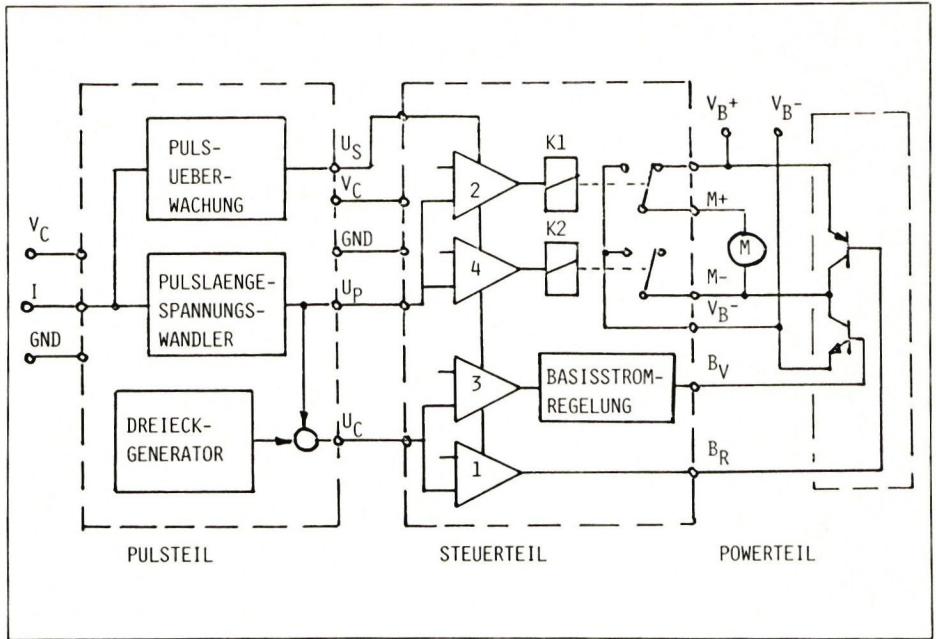
Fig. 1 Block Diagram
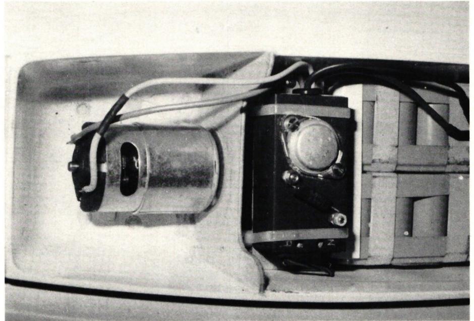
Below: Application in a MAXI-SPEED GRAUPNER 426 12-cell battery: Imax = 19 A
As Up or Uc increases, the upper peaks of Uc trigger comparator 1, the upper power transistor turns on, and current flows through the motor in the opposite direction (Fig. 2e). At the end stop, the duty cycle is approximately 80% (no speed relay).
In the “Car” version, the threshold of comparator 2 is set so that it triggers just before the rear limit. The upper transistor thus briefly energizes the motor (even with a variable duty cycle) via relay K1. This slows the motor down without drawing power from the battery. At the rear stick limit, comparator 1 and relay K1 switch, and the motor now runs backward at a constant speed.
(Fig. 3)
Pulse I from the receiver is to be converted into a ripple-free voltage proportional to the pulse width. This is achieved here using a trailing monostable multivibrator: The integrator (IC2, C4) generates the pulse-dependent voltage Up, which, via R12, adjusts the monostable multivibrator (IC1) so that its output pulse matches the input pulse I. R11 is used to vary the basic time constant of the monostable multivibrator, and R12 is used to vary the integrator’s deflection. This allows the controller to be adjusted to the pulse lengths of the remote control. R11 affects the neutral position, and R12 affects the maximum deflection. Up must be 46% of the receiver voltage Vc when the stick is in the neutral position, 17% when fully forward, and 70% when fully backward.
The short circuit KV1 allows you to adjust the polarity of the input pulse (negative for Varioprop, positive for most others). Up is fed, on the one hand, to the comparators that actuate relays K1 and K2, and on the other hand, to the summing stage (IC2, IC4). Here, the triangular voltage from the oscillator (IC2, R6–8, C3) is added to Up. The result is the voltage $U_c = U_p + 20\% \text{ pp/triangular}$ . The output pulses from IC1 are monitored by the circuit consisting of H1, R9, R10, C5, C6, D1, and H2: If the input pulse—and thus also the output pulse from IC1—is missing, C5 and C6 are discharged via R9 in approximately 0.1 s, H2 goes into high-impedance mode ($U_s = V_c$), and H3 turns off the supply voltage Vc3 for the optocouplers (H9, 10) and for the relay control (R26, 27, H4, 5). When the pulse appears (transmitter is turned on), H2 becomes conductive after about 3 s (R10, C6), allowing the control loop with the mono to settle to the correct value before the output stage is activated. This prevents unintended deflection of the speed controller.
The thresholds for the comparators (IC5) are derived from the receiver voltage Vc via the voltage divider (R16–21). Since these threshold voltages and the voltages Up and Uc are derived from Vc, the operating points do not shift even with large fluctuations in the receiver voltage.
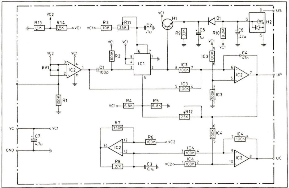
Top: Fig. 3a Schematic diagram of the pulse section
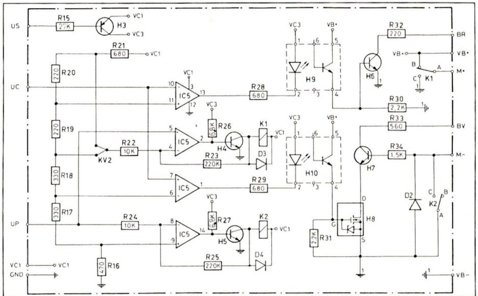
Below: Fig. 3b Schematic diagram of the control section
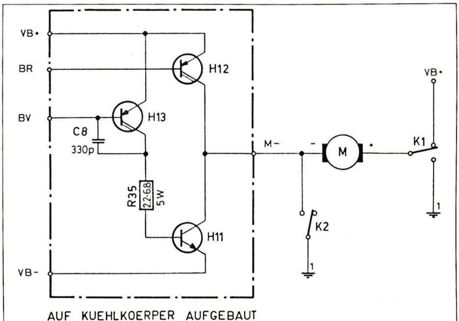
Below: Fig. 3c Schematic diagram of the power section
Using the KV2 jumper, you can set the comparator threshold for the reverse relay to 50% (normal forward/reverse operation) or to 69% (lossless braking). The two relays switch with a hysteresis of 3% (R22, 23, and R24, 25), which prevents the relays from chattering near the switching points.
The output stage for reverse operation consists of a Darlington transistor (H12) and its driver (H6, R32). Its saturation voltage is approximately 1.5 V, which would cause it to become thermally overloaded during prolonged reverse operation (>30 sec).
The main transistor (for forward operation, H11) can be either a single 40-A type (2N5301, TO3: heavier, easier to install) or a configuration of three 15-A types (BD743, TO220). Its drive circuit, together with H13, H7, H8, and R34, forms a control loop: When the output stage is activated (H10 and H8 conducting), the collector voltage of H11 is applied to the base of H7 via R34. H7 remains on as long as the collector voltage of H11 is greater than 0.4 V. Via R33 and H13, H11 receives the base current, which in turn causes its collector voltage to decrease. Thus, only as much base current is generated as is necessary for saturation; in speed mode, it is shut off completely. This configuration achieves extremely high efficiency in the output stage. In this circuit configuration, H11 has a relatively long turn-off
off-time. The saturation voltage control loop is therefore not linear; rather, it settles into a so-called stable oscillation around 0.4 V, which, due to C8, occurs at approximately 20 kHz. R35 limits the power dissipation in H13. Up to power battery voltages of 10 V, it can be replaced with a wire; above that, it should be about 5 ohms.
The design using H11 and H12 has a minor drawback: Some remote controls (e.g., the old “Robbe”) have reversed rotation on the left stick. This problem cannot be solved here by reversing the motor’s polarity, since the speed controller would then operate with the good power amplifier and speed relay for reverse motion, rather than the other way around.
The circuit is foolproof and reliable; about twenty units have been in use for two years to the full satisfaction of their owners.
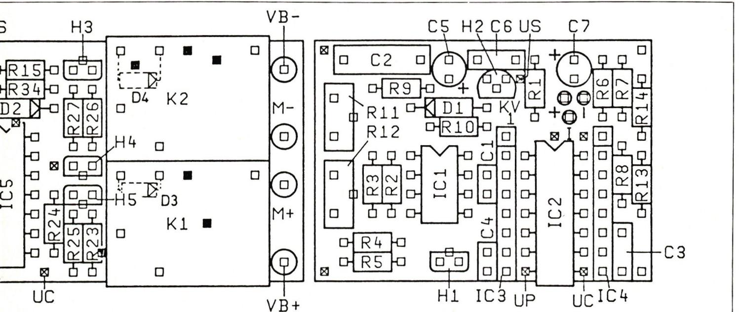
The PCBs are double-sided, but the solder pads are not plated through. Therefore, with the exception of the relays, IC3, IC4, and C2, all components must also be soldered onto the top side.
First, cut the jumper wires as shown in Fig. 4, then mount and solder the components in the following order: layer connections (control section only),
Fig. 5 Assembly Diagram (Scale 4:1)
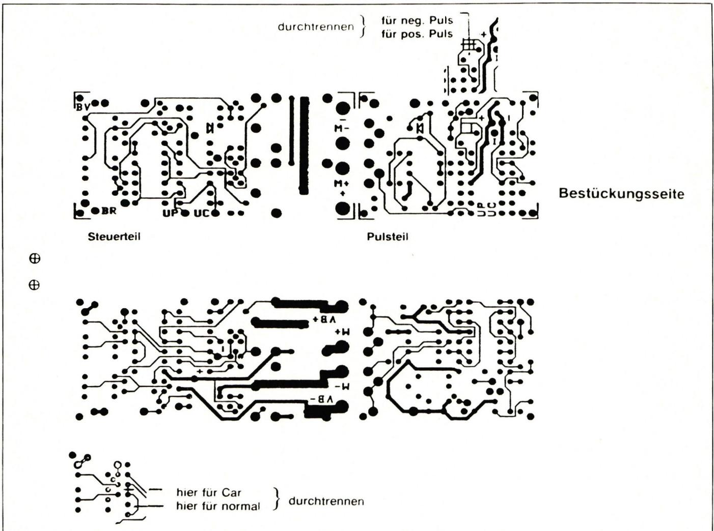
R, D, IC, H, IC3, 4, C2, K, D3, 4 (on the back of the control circuit board), receiver cable (Fig. 5).
The fully assembled circuit boards are tested and roughly calibrated before final assembly. Connect the pulse section to the receiver and use R11 and R12 to set the levels to 17% Vc (max.), 46% Vc (neutral), and 70% Vc (max. reverse) from Up; ensure that Us has low resistance (<50 ohms) relative to Gnd and high resistance (>10 M ohms) when no pulse is present.
If this works, mount the pulse section onto the control section PCB. To do this, solder wires approximately 3 cm long on the pulse section to the points Vc, Gnd, Us, Uc (IC2, Pin 7), Up (IC2, Pin 8), A, and B (PCB connections). Insert these wires into the corresponding points on the control board, press the two boards together as closely as possible, and solder the wires to the top and bottom of the control board (Vc and Gnd only on the bottom). You can now perform the fine-tuning (adjust R11 and R12 so that the relays operate as described in the functional description). The power section is mounted inside the enclosure lid. The transistors must be mounted with mica washers for insulation. If you are not using an enclosure, mount the power section on a 1-mm-thick aluminum sheet measuring 70 x 32. This is secured with M2 screws and spacer tubes in place of PCB connections A and B. If three TO220 transistors are used for H11, they should be placed close together and connected in parallel, pin-to-pin. The Vb+/- and M+/- connections on the control PCB should be fitted with hollow rivets to prevent the PCB from being subjected to excessive stress during the soldering process. The wires should be approximately 2 mm² stranded wire. Ensure good solder joints so that the small voltage drop—which is the goal of the complex circuit design—is not lost in the connections.
CMOS types were used for IC1 (mono) and IC2 (quad op-amp). These have the advantage that their output voltage ranges from zero to the full supply voltage. This ensures that all voltages are percentage-wise independent of the supply voltage Vc (no saturation voltages).
IC3 and IC4 are resistor networks; they contain four 100 kOhm resistors that are very closely matched. This is necessary to ensure that Up is as free of ripple as possible. C2 directly influences the regulator’s open-loop gain; therefore, a polyester capacitor is selected due to its low temperature coefficient.
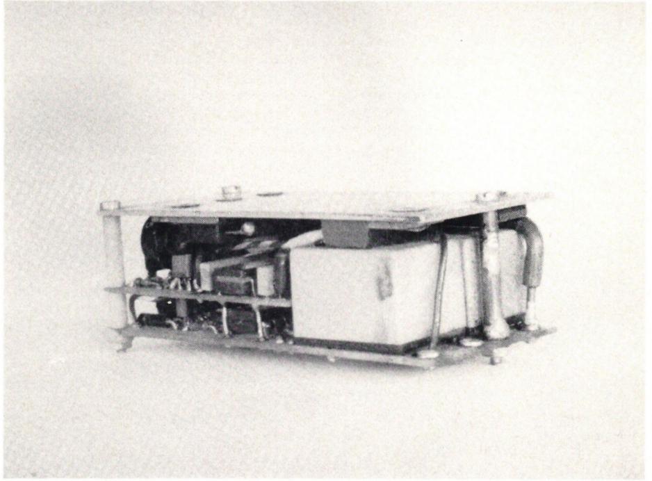
Above: Weight-saving version without a housing. H11 and H12 are mounted without insulation, so the heat sink rests on M-. A brass spacer tube connects to M- on the control board and, together with two additional plastic spacer tubes, forms the mount for the heat sink on the circuit boards. The motor and battery are connected directly to the PCB. The PCBs must be coated with a protective varnish to protect them from dust and moisture.
h (6) ▣ Printed circuit connections (7)
The service life of relays K1 and K2 is specified for only 10 A (200,000 operations); however, since K1 is always de-energized and K2 switches at only 0.4 V, they can safely be loaded with 20 A.
Some components are still relatively new and not available at every electronics store. A component kit is therefore available that includes the semiconductors IC1–5, H1–13, the relays K1 and K2, and the two PCBs (cut to size and drilled).
The finished unit is also available upon request from the author: R. Schmuki, Nebenbachweg 8, CH-9470 Buchs.
Component kit: 79 Swiss francs (specify H11 TO3 or TO220).
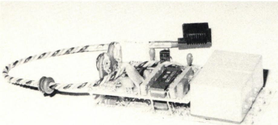
Below: Pulse and control sections fully assembled.
Instead of the motor, connect a 2-watt incandescent bulb to M+ and M-. If you want to be cautious, connect the power battery to V+ and V- via a 1-ohm wire resistor (a current-limited power supply can also be used) to prevent sparks in the event of a short circuit. Then, check the functions again according to the function description and readjust them if necessary:
Neutral position – no relay is engaged, the bulb does not light up.
Forward – the lamp begins to glow.
Full forward – the speed relay engages, and the light is at its brightest.
Reverse – reverse relay engages, lamp is on.
Full reverse – the light is not as bright as at full forward.
In the Car version, the reverse relay engages (and the light comes on) only at full reverse.
If everything worked, the controller is now ready for use.
| R1,2,6 | 100K |
| R3,22,24 | 10K |
| R4,5,26,27 | 6.8K |
| R7 | 390K |
| R8,15 | 27K |
| R9 | 33K |
| R10 | 8.2M |
| R11,12 | 25K Pot |
| R13,14,34 | 1.5K |
| R16 | 470E |
| R17,18 | 330E |
| R19,20 | 220E |
| R21,28,29 | 680E |
| R23,25 | 220K |
| R30,31 | 2.2K |
| R32 | 220E 1/4W |
| R33 | 560E 1/4W |
| R35 | 0-6.8E 5W |
| C1 | 100P Ker |
| C2 | 0.1U MK |
| C3 | 100N Ker |
| C4 | 47N Ker |
| C5 | 1U Ta-E1 |
| C6 | .47U Ta-E1 |
| C7 | 4.7U Ta-E1 |
| C8 | 330P Ker |
| D1,3,4 | 1N4446 |
| D2 | 1N4001 |
| H1,4-7 | ZTX107BL |
| H2,8 | UN0104N3 |
| H3 | ZTX217BL |
| H9,10 | 4N26 |
| H11 3x | BD743B |
| H12,13 | BDW44 |
| IC1 | ICM7555IPA |
| IC2 | ICL7641ECPD |
| IC3,4 | 4308-102-104 |
| IC5 | LM339 |
| K1,2 | ODDH-106D |
| House | TEKO 1/A |
Fig. 6 Parts List
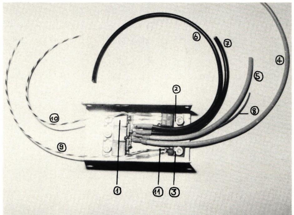
Right: Suggested layout for the power section in the case cover:
- 1 H11 3×TO220
- 2 H12
- 3 H13 with C8
- 4 M- to the motor
- 5 M- to the PCB
- 6 Vb—to the battery
- 7 Vb- to the circuit board
- 8 Vb+ to the PCB (only approx. 0.2 mm²)
- 9 Bv to the PCB
- 10 Br to PCB
- 11 R35 here: 0 ohms
Note: The M+ and Vb+ connections come directly from the PCB.


TEAM MANAGER "THIS" BOSSHARD
 Rodito Nussbaumer

52. 2026 ALPS CUP
 Emil Giezendanner

ATOM, THE NEW DOUBLE-DECKER FROM CPLR
 Matthias Bosshard

INSIGHTS INTO THE HISTORY OF SEAPLANES

34th HAHNENMOOS ALPINE MODEL AIRPLANE CAMP
Res Dauwalder
CORSAIR F4U – A WARBIRD WITH A MEMORABLE LOOK
Jürgen Rosenberger, Jürgen Prinz
SUMMER FUN 2026 AT MG USTER
Martin Wunderli
F3A EUROPEAN CHAMPIONSHIPS IN ST-MACAIRE, FRANCE
Matthias Bosshard
What's New at Leomotion.com

HORIZON HOBBY/LEMACO NEWS: MICRO OV-10 BRONCO 645 MM BY E-FLITE

PRIDE AND GOOD IDEAS
 Markus Nussbaumer

News from HEBU

BY YOUTH, FOR YOUTH
Lorena Betschen
YOU KNOW WHAT I MEAN? 125 YEARS OF THE SWISS AERO CLUB
Emil Giezendanner
SMALL, MODEL-LIKE SAILBOATS
Res Dauwalder
TRY-OUT DAY AT MFV WETTINGEN
Urs Keller
FREE FLIGHT IN THE MIDDLE OF SUMMER
Urs Muntwyler
THE PC-21 STORY
Emil Giezendanner
TWIN TOWN PARTNERSHIP
Wolfgang Voeller
EURO CONTEST GLIDER ACRO TOUR AUSTRIA 2026

WELCOME, NEW MEMBER!
Andrea Bolliger
COUPE DES ALPES – OBSERVE AND LEARN
Rodito Nussbaumer
NEWS FROM HEBU
 Julia Bucher

FROM 0 TO 100
Markus Nussbaumer
NOS REGION – A HUB FOR ELECTRIC AVIATION
Emil Giezendanner
MEMORIES
Wolfgang Völler
Have you almost forgotten about aircraft that take off and land vertically?
Emil Giezendanner
70 YEARS OF THE NIDWALDEN MODEL AIRPLANE CLUB
Martin Barmettler