
The Flight of the Condor
Condor IV: The latest addition from Bayer CNC-modellbautechnik
After building an ASG-29 with a 9-meter wingspan made of carbon fiber, abachi wood, and Styrofoam, I felt the need to once again feel the direct contact of the building materials under my fingers, without the barrier of gloves. What’s more, I missed the smell of freshly cut wood—something that probably only modelers who are approaching retirement can understand!
While flipping through a specialty magazine, I discovered Bayer CNC-Modellbautechnik’s 2007 release, the Condor IV at a 1:3 scale, with a 6-meter wingspan (www.cnc-modellbautechnik.de). Having already built several models from this manufacturer—including its now-famous Minimoa—I knew I wasn’t taking any risks by ordering the new kit. Three weeks after placing the order, I was able to pick up the wooden kit directly in Wettstetten, Germany, and, thanks to H.J. Bayer’s kindness, tour his workshops (see modellflugsport 3/2008).
The Condor is a little-known glider, both among enthusiasts of full-scale vintage aircraft and among modelers. The small number of aircraft built for each version (Condor I through IV) may be the reason for this. But let’s hope that H.J. Bayer’s initiative to bring such a model to market will reignite interest in this creation by Heini Dittmar.
The first Condor, built in 1932 and inspired by the aerodynamic principles that Alexander Lippisch had applied to the construction of the Fafnir, had a wingspan of 17.24 m; it
was to set a remarkable altitude record of 4,350 m, achieved by its builder… without an oxygen mask. The Condor II was equipped with a slimmer, less curved airfoil and also benefited from several other improvements. For the Condor III, the guy wires—a source of drag—were eliminated; the prototype and nine other gliders were built by Alexandre Schleicher. This version became the ultimate competition glider until the outbreak of war. After the war, when gliding was once again permitted in Germany, manufacturers strove to renew the fleet of training gliders, encouraged by the creation of the two-seater category. Drawing on his experience with the first three versions of the Condor, Heini Dittmar modified the Condor III into a two-seater glider, the Condor IV, in 1953. While manufacturers typically used thick airfoils to achieve sufficient height for the main spar, Dittmar used a Gö 532 airfoil profile with a thickness of only 12.5%, a very thin profile at the time for an all-wood construction, tapering to a 12% NACA 0012 profile at the leading edge. To solve the stability problem
On the wing, the manufacturer increased the depth of the main spar, which also increased the glider’s weight to 357 kg. (It is worth noting here that we modelers also used thick airfoils such as the Ritz or NACA to ensure that the wings of our first large gliders—with wingspans of 4 to 5 m, built with a balsa-core structure—were sufficiently strong, before the advent of composites.) To accommodate the second passenger, seated in tandem behind the pilot at the center of gravity, the fuselage was lengthened by 70 cm to 8.44 m. As with almost all versions of his gliders, Dittmar retained a pendulum-type elevator that was not well-liked by pilots. The dimensions of the vertical stabilizer and rudder were significantly increased compared to the Condor III.
Two prototypes were built, followed by five aircraft produced in Ferdinand Schmetz’s workshops in Aachen; subsequently, seven versions with a modified fuselage were built by Alexandre Schleicher. The Condor IV’s glide ratio ranged from 31 to 80 km/h, and its minimum sink rate was 0.71 m/s at 70 km/h—performance figures that were quite acceptable for the time. Currently, of the 14 gliders built, only a few are believed to remain, mostly of the Schleicher version.
The version chosen by H.J. Bayer is that of the first series, with the wing mounted on a pylon fuselage—a feature later eliminated in Schleicher’s subsequent designs. The kit I purchased was the fifth one supplied by H.J. Bayer, which explains certain inaccuracies in the
Cutting out a few parts. In the meantime, feedback from modelers has been taken into account and the errors corrected. Another minor drawback was that no assembly instructions were available yet, but with an illustrated list of the various parts, well-drawn plans, and the experience gained from building the Minimoa from the same manufacturer (see Modellflugsport 4/2004), only a lack of time or space might potentially pose a problem. It should also be noted that a step-by-step construction guide is not essential, as the patented technology—called Frame Lock® by its inventor—greatly simplifies the process, which largely consists of assembling parts, much like a puzzle, and does not require a 1:1 scale plan.
The quality of the wood in my kit was superb, as was that of the milled and deburred parts. The 2-mm balsa formers, already glued to the required lengths and widths, were uniformly hard—a rarity worth noting. For gluing, white glue is recommended, although you can use ultra-fast cyanoacrylate glue to secure the
and other ribs in place. However, the slight time savings do not make up for the quality of the bond achieved with white glue. It’s best to use water-resistant glue—not in anticipation of a landing in the stream that all too often borders flying fields, but to withstand any warping corrections by moistening the formwork wood (I speak from experience!). Furthermore, the fuselage formwork must be built using the ironing technique, which requires white glue.
To get started, I began construction with the rudder,
adding a crossbrace to cap the ribs, just like on the full-scale glider I chose to replicate (see below). The pendulum elevator followed. I replaced the brass hinge pins with lighter carbon tubes and built both halves simultaneously on the workbench, connected by the two hinge tubes. After the formwork had dried, I sawed the tubes between the two parts of the stabilizer, thus avoiding any misalignment between the two parts (Fig. 1).
As the saying goes: “Appetite comes with eating,” and after working on the tail sections,
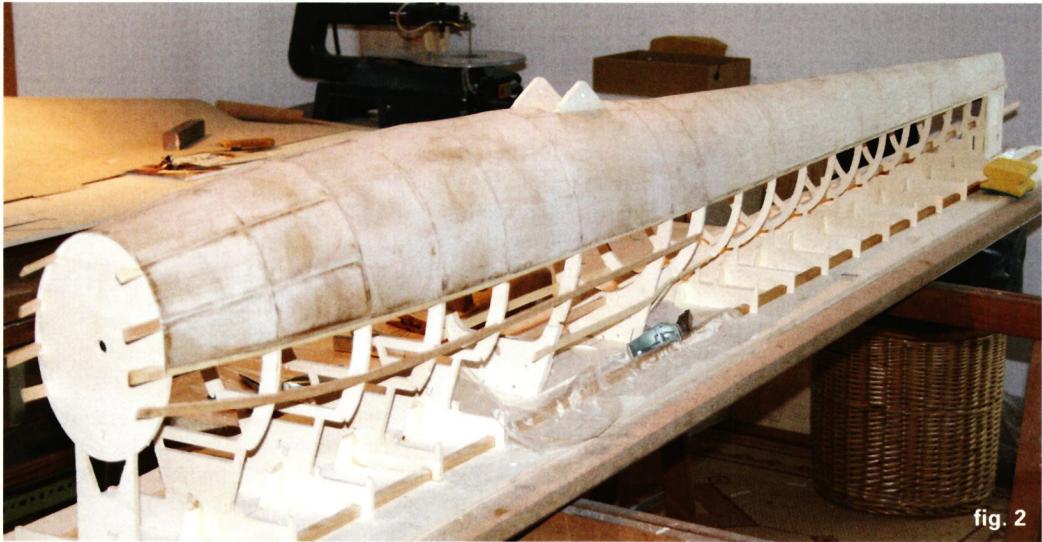
tail sections, I was hungry enough to start on the fuselage. But then, hadn’t I let my eyes get bigger than my stomach? Twenty pairs to align over a length of nearly 250 cm, all framed with 0.6 mm plywood! Fortunately, the technique developed by H.J. Bayer calls for a single-step construction process, without having to join two separately built halves. Each rib is equipped with a “foot” that slots onto two strips fixed parallel to the work surface; since the fuselage is built upside down, I cut a notch in one end of the work surface to accommodate the rudder spar that was sticking out. Once the “feet” of the frames were secured to the work surface with a few drops of cyanoacrylate, I glued the stringers in place, taking care to alternate the left/right gluing of each stringer to avoid any tension that might cause the structure to twist (Fig. 2). All that remained was to form the entire structure with 0.6 mm plywood sheets using the ironing technique, as previously described in my article on building the Minimoa: the formwork is placed on the ribs, which have been generously coated with white glue, and bonded by applying an iron set to maximum heat:
The water in the glue evaporates under the heat, and the two surfaces bond together almost instantly. Here, too, it’s essential to alternate gluing left and right to avoid tension. When the fuselage’s curvature becomes too great to be formed in a single piece, we use small panels that are glued one after another. The time spent on this work is much shorter than the hesitation one might feel about starting to assemble this patchwork! I’ve been told that after the publication of my article on the Minimoa—in which I suggested buying his wife a new iron so he could use her old one— several wives tried to convince their husbands to build an all-wood vintage glider (I haven’t been able to verify this anecdote)!
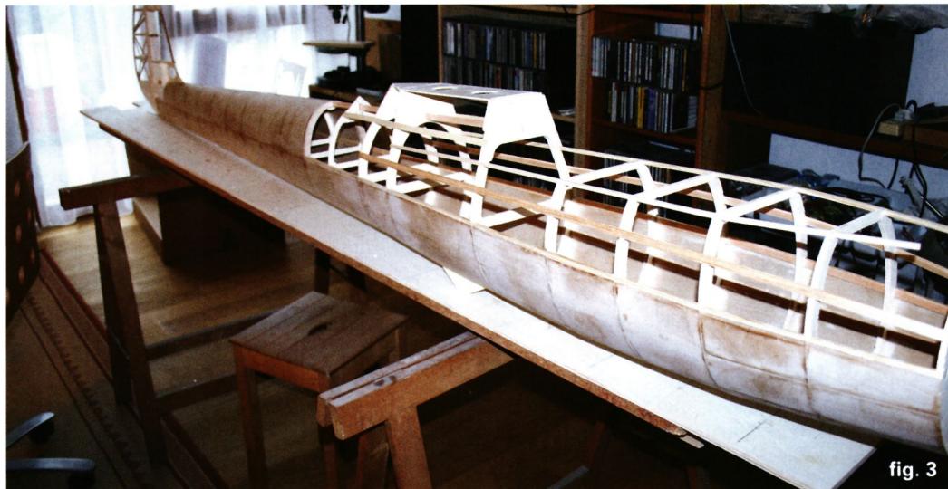
Once the formwork is complete, cut off the “feet” of the stringers, flip the glider over, and form the upper half of the fuselage (Fig. 3). Before forming the vertical stabilizer, you must install the elevator servo. I didn’t follow the suggestion to place it in the fuselage under the stabilizer because of the insufficient depth available; only a wing micro-servo—which, in my opinion, is too weak to actuate a pendulum stabilizer—could be used.
A 20 dm² wing could fit there. I installed an HS-645 MG servo in the rudder, above the horizontal stabilizer. I also replaced the Novotex hinge included in the kit with a piece cut from a 2-mm fiberglass sheet. After that, you can’t help but admire your work—with the horizontal stabilizer and rudder installed—to see “what it looks like.” That’s when you realize just how massive this beast is, and you’re glad you thought about transportation before buying the model—unless, of course, you deliberately hid the problem from your wife to justify buying a new car: you have to fit 275 cm of fuselage into the car without removing the vertical stabilizer.
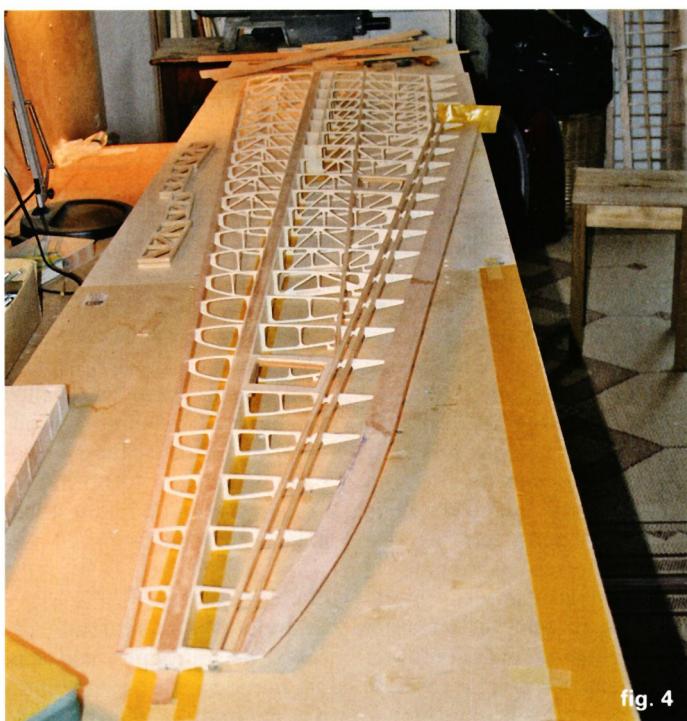
Once the main course has been digested, we can move on to dessert: the wings. They are constructed in two parts because of their so-called “seagull” shape, which results from the dihedral break. (It appears that the full-scale Condor is the last glider built with this type of wing.) The first part is a rectangle 50 cm deep, constructed by placing the upper surface of the ribs on the workbench. Each rib has a foot that ensures the trailing edge is aligned with the workbench. The spars are
made up of several pine strips that must be glued together with great care to ensure the wing’s alignment. Once the spar was secured to the work surface—with a sheet of plastic film inserted between them to avoid any unpleasant surprises when removing the wing—I glued each rib to the spar using white glue, securing the foot directly to the work surface with a drop of cyanoacrylate. This way, each rib is immediately secured, and construction can proceed
very quickly. The balsa formwork is added before removing the wing from the work surface, glued using the ironing technique. It is not necessary to wet the balsa to make it conform to the shape of the ribs if you proceed by starting from the spar and working toward the leading edge (Fig. 4). Let it dry for 24 hours before removing the wing from the work surface, and do not go on vacation before gluing the upper surface spar and its formwork to prevent warping. Given the size of the wing—whose dihedral further increases its overall dimensions—you might be tempted to build it in two sections. However, the joint designed to connect the two wing halves—consisting of a metal core and open-cell plywood side panels—is difficult to fit and would likely be too unstable to provide a removable connection between the two wings. If you wish to build the wing in two parts, it would be preferable to divide the second half of the 2-meter-wingspan wing, after the air brakes, by inserting, for example, a tube-and-carbon-fiber-rod connector between the spars. Personal-
In the end, I opted for a one-piece wing. The air brakes extend above and below the wing; they are made of plywood, hinged with Novotex parts that are too brittle for my liking. I decided to forego the exact scale model look by installing conventional aluminum air brakes that extend only from the upper surface of the wing. For the articulation of each aileron, I installed two servos, contrary to the plan.
Once the four wing halves were finished, all that was left to do was glue them together in pairs to complete the glider’s structure. With the fuselage resting on the ground, I attached the first two wing halves to the fuselage using the provided hardware, then slid the other two halves onto the cleats inserted between the spars—but did not glue them in place yet. I then measured the ground clearance of the leading and trailing edges at various distances from the fuselage and compared the values obtained on both sides. By adjusting the wing struts between the spars, I was able to achieve symmetrical dihedral on both wings by inserting small shims into the struts. Then, using a string attached to the top of the vertical stabilizer, I performed what our Gallic friends call “setting the cross.” Even today, I wonder whether this expression refers to the model or its builder: whenever I changed one parameter, another would shift, and I had to start all over from scratch—including adjusting the wing’s angle of attack
of the wing. When everything was finally properly aligned, I had to remove the two outer wings to epoxy the spars into their sleeves while double-checking all the alignments; needless to say, I didn’t use any 5-minute epoxy. By the end of the process, I realized that my repertoire of swear words had been enriched with a few new gems—go figure!
After that ordeal, I thought all that was left was to enjoy the icing on the cake by assembling the canopy. Alas, the icing turned out to be bitter. The canopy consists of two parts: the canopy itself, which covers the cockpit, and a second part—attached to the first—that follows the leading edge of the wing all the way to the spar, allowing the second passenger to see where the first passenger is heading. I first fitted the main canopy to the fuselage, temporarily securing it to its frame, only to find that the shape of the second section did not align with the main canopy when it was adjusted to the leading edge. After numerous unsuccessful attempts, I decided to order two new parts, and I completed the assembly by first attaching the second section to the leading edge and then fitting it to the fuselage (Fig. 5).
The full-scale model I chose to replicate is the one that participated in the 11th Oldtimer Meet at Hahnweide
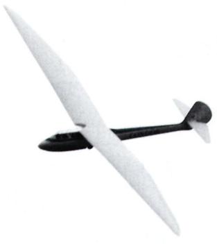
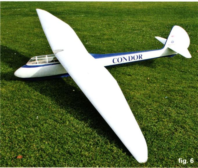
in 2001, as illustrated in J. Gassebner’s book *Die schönsten Oldtimersegelflugzeuge* (Motorbuch Verlag, 2002). I covered all the structural parts with white Oratex, which effectively mimics the texture of canvas. The fuselage was reinforced with very fine woven glass twill, 100 g/m², bonded with an epoxy resin diluted with 20% methanol (www.swiss-composite.ch). After rough dry sanding, I applied a second coat, which was wet-sanded. There was no need for a pore filler, as the resulting surface was so uniform. The white and blue colors were applied with an aerosol spray. Total weight of the model in flight-ready condition: 14.6 kg, or approximately 70 g/dm² (Fig. 6).
Forced to stay away from the airfields for more than three months, I decided to let a test pilot—my friend Urs—take the controls for the maiden flight. With the tow bar attached under the nose of the glider (I decided against the double tow bar attached to both sides of the fuselage, as on the original),
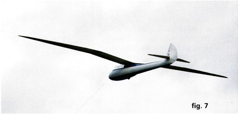
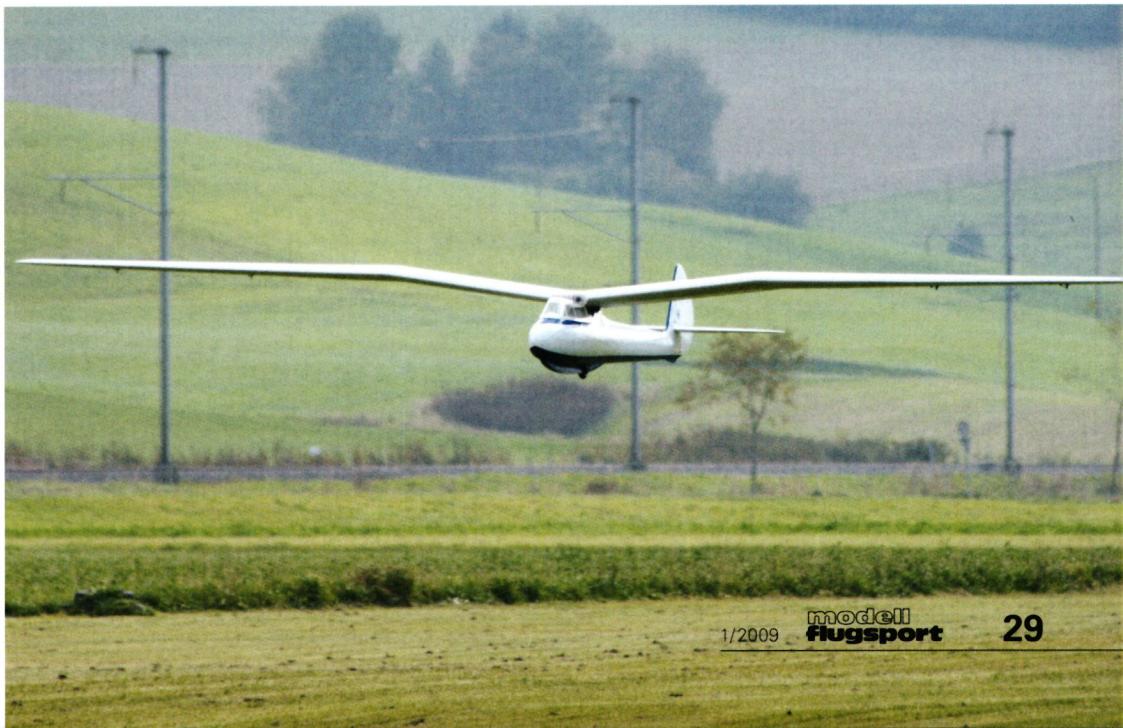
allowed our trusty tow pilot, Hans-Ueli, to open the throttle and taxi less than 10 meters before the Condor left the ground. From that moment on, all that was left was to admire the flight of the beast, which, according to the pilot, required no corrections whatsoever once released (Figs. 7 and 8). I was able to confirm the excellent flight characteristics that Urs had pointed out to me by taking the controls myself. What’s most surprising is how little control input is needed to maneuver the aircraft, which can be piloted using the rudder alone. The only minor drawback for the pilot is getting used to the pendulum-style elevator control, which is slightly sluggish due to the fuselage’s long lever arm, and landing—where one must remember that the center of gravity is located in front of the wheel. In summary, one can simply say that the Condor’s flight is exceptional, both in terms of its qualities and its elegance. It’s a model to build and enjoy indefinitely—unless it crashes...
dominiquebaer@gmail.com


News from HEBU

TEAM MANAGER "THIS" BOSSHARD
 Rodito Nussbaumer

YOU KNOW WHAT I MEAN? 125 YEARS OF THE SWISS AERO CLUB
 Emil Giezendanner

F3A EUROPEAN CHAMPIONSHIPS IN ST-MACAIRE, FRANCE
 Matthias Bosshard

52. 2026 ALPS CUP
Emil Giezendanner
PRIDE AND GOOD IDEAS
 Markus Nussbaumer

ATOM, THE NEW DOUBLE-DECKER FROM CPLR
Matthias Bosshard
CORSAIR F4U – A WARBIRD WITH A MEMORABLE LOOK
Jürgen Rosenberger, Jürgen Prinz
SUMMER FUN 2026 AT MG USTER
Martin Wunderli
TRY-OUT DAY AT MFV WETTINGEN
Urs Keller
TWIN TOWN PARTNERSHIP
Wolfgang Voeller
BY YOUTH, FOR YOUTH
Lorena Betschen
SMALL, MODEL-LIKE SAILBOATS
Res Dauwalder
What's New at Leomotion.com

HORIZON HOBBY/LEMACO NEWS: MICRO OV-10 BRONCO 645 MM BY E-FLITE

COUPE DES ALPES – OBSERVE AND LEARN
Rodito Nussbaumer
EURO CONTEST GLIDER ACRO TOUR AUSTRIA 2026

INSIGHTS INTO THE HISTORY OF SEAPLANES

34th HAHNENMOOS ALPINE MODEL AIRPLANE CAMP
Res Dauwalder
WELCOME, NEW MEMBER!
Andrea Bolliger
FREE FLIGHT IN THE MIDDLE OF SUMMER
Urs Muntwyler
THE PC-21 STORY
Emil Giezendanner
NEWS FROM HEBU
 Julia Bucher

FROM 0 TO 100
Markus Nussbaumer
MEMORIES
Wolfgang Völler
NOS REGION – A HUB FOR ELECTRIC AVIATION
Emil Giezendanner
Have you almost forgotten about aircraft that take off and land vertically?
Emil Giezendanner
DO YOU KNOW WHAT I MEAN IN THE LAND OF SMILES?
Emil Giezendanner