
Safety in Working with Electric Drives
The rise of electric propulsion in model aviation continues. With it, safety requirements are also changing. At Leomotion (www.leomotion.com), we are not only suppliers of electric powertrains, but we also manufacture motors in-house in the Zurich Oberland for applications in both the RC and industrial sectors.
In the following, we’d like to shed light on certain aspects to enhance understanding of electric propulsion and thereby contribute to safe operation in model aviation.
The golden rule: Once the flight battery is connected, the drive system must be considered “live” until it is disconnected again—regardless of any safety measures in place. If you always expect the motor to start up accidentally, you won’t be caught off guard.
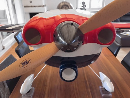
The electric motor delivers high torque even at low speeds, which can cause serious injuries ranging from cuts to the severing of limbs—
can cause injury. For your own safety, we strongly recommend removing the propeller during test runs, troubleshooting, or any other work on the powertrain. Always remember: As soon as the power battery is connected, stay away from the propeller—the propulsion system is always considered “live.”
State-of-the-art controllers are internally protected so
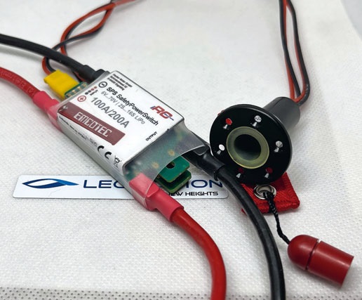
the motor will not start if there is no valid idle throttle signal. As an additional safety measure, electronic switches—also known as solenoid switches—can be installed in the power supply line. Programming the remote control to explicitly enable the throttle channel via a switch on the remote control is also a widely used method. Before connecting the flight battery, it is always recommended to check that the throttle lever is in the idle position.
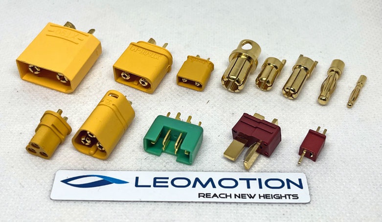
Choose a connector system that is also suitable for the planned maximum current. The higher the current, the larger the connector and cable cross-section must be. The smaller the cross-sectional area of the connector, the higher its contact resistance. As a result, power losses at the connector increase quadratically with the current. The connector becomes warm. If it is undersized, the connector will become so hot that the solder joint on the cable softens and
the plug itself “desoldered.” A reverse-polarity-protected connector offers additional protection against incorrect battery connection. If multiple battery packs are connected in series to form a larger battery (e.g., two 6s packs are connected to form a 12s pack), it is not uncommon for the positive terminal of one battery to be connected to the negative terminal of another battery, resulting in a short circuit. This causes a spark with extremely high currents, which not only permanently damages the connector system but can also lead to severe burns on the fingers.
Concentration and appropriate caution are always required when connecting the battery.
The controller generates a rotating alternating current field from the battery’s DC voltage to drive the motor. This rotating field must always be in sync with the motor’s rotational speed. Modern controllers measure what is known as the zero-crossing of the open phase to achieve this. If a delay in the zero-crossing is detected, the frequency of the generated rotating field is adjusted accordingly. If the controller’s frequency and the motor’s rotational speed are too far apart, this leads to what is known as miscommutation—the controller loses synchronization, and the motor begins to screech or stutter.
The cause is usually improper controller programming (incorrect timing, inappropriate PWM frequency) or poor or even cold solder joints.
It is essential to avoid a motor screeching or stuttering. Immediately return the throttle to the idle position. This
Incorrect commutation leads to very high voltage spikes induced by the motor and can cause lasting damage to the controller’s three-phase bridge (FETs in the driver stage), potentially causing the controller to burn out. The motor must respond to throttle input cleanly and without delay across the entire speed range.
The timing determines the advance angle of the zero-crossing mentioned above. This is comparable to the advance
in an internal combustion engine. Timing can also be used to influence the rotational speed within a limited range. A higher timing increases the speed and thus the power consumption. Beyond a certain point, the speed will no longer increase; only the power consumption will rise—efficiency decreases, and the motor heats up unnecessarily. The lowest current is achieved with a timing of zero degrees. The optimal timing depends largely on the number of magnetic poles and the impedance of the motor. As a rule of thumb
for motors with up to 14 poles, a timing of approximately 1.5 × the number of poles has proven effective. For motors with more than 14 poles, a timing of 20–25° is usually optimal. Specific information can be obtained from the motor manufacturer.
Do not set the controller too close to its limit; allow for a sufficient margin between the expected current and the controller’s limit. The controller heats up due to its power loss, which increases proportionally to the square of the current. The heat
must be able to dissipate this heat into its surroundings; otherwise, it will continue to heat up until the thermal protection trips or it even burns out. Heat dissipation is improved by airflow and a heat sink.
Due to the nature of pulse-width modulation, significantly more power loss occurs in the upper partial-load range than at full controller opening. Keep these points in mind for your specific design and size your controller accordingly. As a rule, a 20% safety margin is sufficient.
Due to the controller’s pulse-width modulation (PWM), even straight supply wires act like coils. As a result, when the PWM’s falling edge occurs, a voltage is induced that is significantly higher than the battery voltage. The magnitude of the induced voltage increases with the length of the lead wire and can damage the capacitors on the controller, causing the controller to fail.
If you need to extend the cables between the controller and the battery, it is essential to install additional capacitors as close as possible to the controller’s input to ensure better
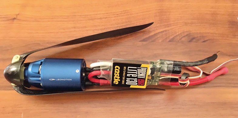
The winding wires are coated with heat-resistant varnish for insulation. These wires are usually routed to the outside, tinned, and serve as motor terminals. NEVER trim these terminals, because the varnish can only be removed from the wires using special chemicals to ensure proper tinning. It is not uncommon for the motor to be beyond repair. To mount the controller in a space-saving manner, form a loop as shown in the illustration. This keeps the cables short and minimizes signal loss.
An idle test at full operating voltage proves nothing and only causes the motor to overheat. If an idle test—that is, a test run without an applied load (e.g., a propeller)—is performed, the motor shaft delivers no power, and the applied mechanical shaft power is effectively 0 W. Consequently, the efficiency is 0%, and the total
applied electrical power is converted into power loss and heat. Motors with relatively high no-load current can thus become thermally overloaded even when idling and suffer permanent damage.
If a no-load test is nevertheless necessary—e.g., to check whether everything is running normally—we recommend selecting an operating voltage of around 5 V to 10 V (e.g., a 2S or 3S battery) to avoid placing an unnecessary load on the motor. The test run should be brief (less than 10 seconds), with an adequate cooling period in between.
We recommend always using the remote control's fail-safe function
and to program the throttle channel to idle in the event of signal loss. This reduces the risk of injury from the propeller in the event of a complete loss of signal to the model.
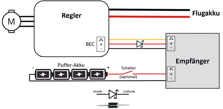
Relying exclusively on a BEC (Battery Eliminator Circuit) for power supply carries the risk of losing control if problems arise with the controller. Therefore, a backup power supply is highly recommended. This can be easily and inexpensively implemented using a Schottky diode and a small backup battery. Specialty stores also carry sophisticated electronic
backup systems (e.g., OptiPower or SafeGuard) that not only provide the necessary power but also charge the backup battery from the functioning BEC and can be easily switched from one model to another. The premium option is a power splitter with an additional backup battery.
If the ESC’s BEC is not being used, it can be easily deactivated by pulling the positive terminal out of the connector and bending it over. Secure the exposed contact to the cable with a piece of tape and insulate it.
At Leomotion, we’re not only specialists in electric propulsion—we also live by the motto: “Nothing is impossible.”
We’d be happy to advise you on your specific propulsion issue so you can enjoy the flight performance of your new model. www.leomotion.com
Report in French: https://www.modellflug.ch/FR/home
Report in Italian: https://www.modellflug.ch/IT/home


TEAM MANAGER "THIS" BOSSHARD
 Rodito Nussbaumer

YOU KNOW WHAT I MEAN? 125 YEARS OF THE SWISS AERO CLUB
 Emil Giezendanner

F3A EUROPEAN CHAMPIONSHIPS IN ST-MACAIRE, FRANCE
 Matthias Bosshard

News from HEBU

SUMMER FUN 2026 AT MG USTER
Martin Wunderli
TRY-OUT DAY AT MFV WETTINGEN
Urs Keller
52. 2026 ALPS CUP
Emil Giezendanner
BY YOUTH, FOR YOUTH
Lorena Betschen
ATOM, THE NEW DOUBLE-DECKER FROM CPLR
Matthias Bosshard
CORSAIR F4U – A WARBIRD WITH A MEMORABLE LOOK
Jürgen Rosenberger, Jürgen Prinz
SMALL, MODEL-LIKE SAILBOATS
Res Dauwalder
What's New at Leomotion.com

TWIN TOWN PARTNERSHIP
Wolfgang Voeller
EURO CONTEST GLIDER ACRO TOUR AUSTRIA 2026

INSIGHTS INTO THE HISTORY OF SEAPLANES

34th HAHNENMOOS ALPINE MODEL AIRPLANE CAMP
Res Dauwalder
WELCOME, NEW MEMBER!
Andrea Bolliger
HORIZON HOBBY/LEMACO NEWS: MICRO OV-10 BRONCO 645 MM BY E-FLITE

COUPE DES ALPES – OBSERVE AND LEARN
Rodito Nussbaumer
PRIDE AND GOOD IDEAS
 Markus Nussbaumer

FREE FLIGHT IN THE MIDDLE OF SUMMER
Urs Muntwyler
THE PC-21 STORY
Emil Giezendanner
NEWS FROM HEBU
 Julia Bucher

FROM 0 TO 100
Markus Nussbaumer
MEMORIES
Wolfgang Völler
NOS REGION – A HUB FOR ELECTRIC AVIATION
Emil Giezendanner
Have you almost forgotten about aircraft that take off and land vertically?
Emil Giezendanner
70 YEARS OF THE NIDWALDEN MODEL AIRPLANE CLUB
Martin Barmettler