
DIONYS RC Sailboat
For years, I had been looking for a model that fell between the AMIGO and the many 3-meter gliders in size, one that could be used universally for slope and high-altitude launches as well as for motor gliding. That is, until I found the PIVIERE from Simprop. However, this model did not achieve the commercial success I had hoped for, which led to it being discontinued after only two years. The reason for this was certainly the poor quality of the fuselage material and the other plastic components.
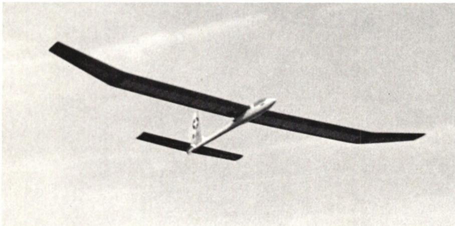
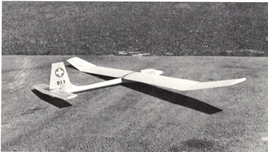
After some hesitation, I decided to buy the kit. However, I modified the model until it met my expectations. I altered and simplified the fuselage and vertical stabilizer, and slightly enlarged the wings. This resulted in the following specifications:
Wingspan 254 cm
, fuselage length 123 cm
Flight weight: approx. 1,300–1,500 g, depending on the design and control system. If you want to make the most of the wood you’ve purchased, you can extend each wing section by one rib—that is, by about 19 cm—without having to enlarge the horizontal stabilizer, since it’s already slightly oversized.
Fuselage: Since the fuselage is available as a pre-built part, the work is essentially limited to the internal components and the vertical stabilizer. First, we pour 100 g of lead shot into the nose of the fuselage using Araldit. Then we measure out the space needed to accommodate the battery and receiver and construct the servo mount as a longitudinal strut, as is common with plastic fuselages. Next, we build the
vertical stabilizer up to and including the primer coat and the mounted rudder horn. We glue this into the fuselage cutout and secure it with masking tape at the base of the vertical stabilizer. This ensures proper installation. Then we align the control linkage (5 x 5 mm balsa).
For the elevator, drill a hole of approximately 10 mm at the rear of the fuselage and file it out as needed so that the linkage does not interfere anywhere. Two strips of Tesamoll are glued between the horizontal stabilizer and the fuselage. The burr and the slight taper of the stabilizer mounting surface—which is essential for fuselage construction—are therefore not filed away. (Except for any interfering burrs.)
Only once the linkages fit properly do we glue on the wing supports (4+5). These also serve to reinforce the fuselage. At the same time, we also glue in the dowels for attaching the wings.
The canopy can be cut out with a jigsaw if it interferes with the linkage or the servos. The method of attaching the canopy is left to the discretion of each builder of this model.
All glue joints with the fuselage must be made with Araldit.
Wings: First, glue the brass tubes (50) into the main spar (36) using Araldit and attach the plywood reinforcements (47+48). After cutting the end strips and the main spars, glue the lower skin to the main spar. Then insert the ribs, but glue them only to the main spar and simultaneously to the end strip. (Do not glue them to the planking.) We apply the necessary bevel to the nose strip (using a plane or sandpaper), glue it to the ribs, and allow the glue joints to dry thoroughly. Only then do we apply glue between the ribs and the lower planking, as well as to the now-beveled side of the nose strip. We then tack the lower planking to the nose strip using masking tape or other adhesive tape. Next, we plane the top of the leading edge at an angle so that it is flush with the ribs, and then attach the upper planking. We also secure this with adhesive tape around the leading edge, as well as to the main spar and the lower planking. After tacking the upper planking in place, the wing halves are weighted down on a flat surface at the trailing edge and at the level of the main spar so that any warping can self-correct before the glue dries. This is an advantage of this construction method compared to the usual pin-fastening technique. It eliminates the various holes caused by pin pricks. The outer wings are built in the same way, though it is not necessary to install a strut. When assembling the two wing halves, the filler pieces—which are not numbered on the plan—are cut from leftover 5-mm balsa wood, fitted, and glued in place.
Horizontal Stabilizer: For the horizontal stabilizer, we make sure to use lightweight wood for all parts. The elevator is cut from 8 mm balsa and sanded into the desired shape.
Covering: When covering with paper or silk, the wood should first be coated once with a hard primer and then lightly sanded with 220-grit sandpaper.
Monokote adheres better to unvarnished wood.
Test Flight: If the model is well-balanced, the test flight should go smoothly. Nevertheless, we should choose a calm day. If your model turns in a bit too much against the wind, I recommend shimming the front of the horizontal stabilizer by about 1 mm before adding more lead.
I hope you’re just as enthusiastic about this model as my friends and I are.
| Part | Designation | Quantity | Material | Thickness |
| 1 | Polyester hull | |||
| 2 | Polyester canopy | |||
| 3 | Anchor | 2 | Beech | 6 mm |
| 4–5 | Wing support (fuselage reinforcement) | Plywood | 0.8 mm | |
| 6–7 | Vertical stabilizer | Balsa | 5 mm | |
| 20 | Primary ribs | 2 | Plywood | 3 mm |
| 21 | Ribs | 4 | Balsa | 2 mm |
| 21 | ribs | 2 | Plywood | 2 mm |
| 22 | Ribs | 2 | Balsa | 2 mm |
| 23 | ribs | 8 | Balsa | 2 mm |
| 24 | ribs | 20 | Balsa | 2 mm |
| 25 | Ribs | 4 | Balsa | 2 mm |
| 26–33 | ribs | 2 each | Balsa | 2 mm |
| 34–35 | Struts | 2 each | Balsa | 10 x 15 mm |
| 36–37 | Struts | 2 each | Balsa | 5 x 25 or 5 x 20 + 5 x 5 mm |
| 38–39 | End strips | 2 each | Balsa | 7 x 28 mm |
| 40 | Reinforcements | 2 | Plywood | 0.8 mm |
| 41 | End blocks | 2 | Balsa | 8 mm |
| 42–46 | Facing | 4 each | Balsa | 1.5 mm hard |
| 47–48 | Strut reinforcements | 4 each | Plywood | 0.8 mm |
| 49 + 52 | Steel wire | 4 mm | 5 x 4.2 mm | |
| 60 + 51 | Brass tube | 4 x 10 cm | 0.8 mm | |
| 53 | depending on the variant | 2 | Plywood | 2 mm |
| 54 | ribs | 4 | Balsa | 2 mm |
| 55 | Ribs | 12 | Balsa | 6 x 6 mm |
| 56 | Spine | 1 | Balsa | 3 x 12 + 1.5 mm |
| 57 | Spine | 1 | Balsa | Filler |
| 58 | Spine | 1 | Balsa | 8 x 13 mm |
| 59 | Elevator | 1 | Balsa | 8 mm, lightweight |
| 60 | Facing | 2 | Balsa | 1.5 mm lightweight |
| 61 | Facing | 2 | Balsa | 1.5 mm lightweight |
| 62 | End blocks | 2 | Balsa | 5 mm |
Accessories: Hinges, control linkage, rudder horns, possibly a ball joint for the elevator control, and fabric for covering the airframe. Lead shot, approx. 100 to max. 150 g.
| Fuselage with canopy | |
| approx. 10 dm² of 0.8 mm plywood | 4, 5, 40, 47, 48, 53 |
| approx. 2 dm² of 2-mm plywood | 21 |
| approx. 2 dm² of 3-mm plywood | 20 |
| 5 pieces of 2-mm hard balsa for all ribs | 21–33 54–55 |
| 7 medium-density 1.5 mm balsa for the skin | 42, 43, 44, 45, 46 |
| 1 1.5 mm light balsa for skinning | 60, 61 |
| 1 5 mm medium balsa | 6, 7, 62 |
| 1 8 mm light balsa wood | 59, 41 |
| 3 balsa spars 6 x 6 medium | 56, + control linkage |
| 3 balsa spars 10 x 15, medium | 34, 35 |
| 3 balsa spars 5 x 25, hard (possibly 5 x 20 + 5 x 5) | 36, 37 |
| 1 balsa spar 3 x 12, soft | 57 |
| 1 balsa stringer 8 x 13 (light) | 58 |
| 3 balsa end strips 7 x 28, hard | 38, 39 |
| 1 beech round rod, 6 mm | 3 |
| 1 brass tube 5 x 4.2 mm | 50, 51 |
| 1 4-mm steel wire | 49, 52 |
| 1 Rudder horn | |
| 1 ball joint (Graupner 3747) (replacement fork connector 3525) | |
| 2 rudder levers with steel wire at least 20 cm long | |
| 2 rudder levers with short steel wire | |
| 6 hinges | |
| Covering materials | |
| Paper covering is recommended; Monokote is acceptable in terms of strength. | |
| Approx. 150 g of lead shot | (Pour into the nose of the fuselage) |
| Rubber bands, 100 mm wide | (for attaching the wings) |
| Rubber bands, 60 mm wide | (Tail assembly attachment) |


News from HEBU

TEAM MANAGER "THIS" BOSSHARD
 Rodito Nussbaumer

SUMMER FUN 2026 AT MG USTER
Martin Wunderli
SMALL, MODEL-LIKE SAILBOATS
Res Dauwalder
TRY-OUT DAY AT MFV WETTINGEN
Urs Keller
What's New at Leomotion.com

52. 2026 ALPS CUP
 Emil Giezendanner

ATOM, THE NEW DOUBLE-DECKER FROM CPLR
 Matthias Bosshard

INSIGHTS INTO THE HISTORY OF SEAPLANES

YOU KNOW WHAT I MEAN? 125 YEARS OF THE SWISS AERO CLUB
Emil Giezendanner
34th HAHNENMOOS ALPINE MODEL AIRPLANE CAMP
Res Dauwalder
CORSAIR F4U – A WARBIRD WITH A MEMORABLE LOOK
Jürgen Rosenberger, Jürgen Prinz
F3A EUROPEAN CHAMPIONSHIPS IN ST-MACAIRE, FRANCE
Matthias Bosshard
HORIZON HOBBY/LEMACO NEWS: MICRO OV-10 BRONCO 645 MM BY E-FLITE

PRIDE AND GOOD IDEAS
 Markus Nussbaumer

EURO CONTEST GLIDER ACRO TOUR AUSTRIA 2026

BY YOUTH, FOR YOUTH
Lorena Betschen
FREE FLIGHT IN THE MIDDLE OF SUMMER
Urs Muntwyler
THE PC-21 STORY
Emil Giezendanner
TWIN TOWN PARTNERSHIP
Wolfgang Voeller
WELCOME, NEW MEMBER!
Andrea Bolliger
COUPE DES ALPES – OBSERVE AND LEARN
Rodito Nussbaumer
NEWS FROM HEBU
 Julia Bucher

FROM 0 TO 100
Markus Nussbaumer
MEMORIES
Wolfgang Völler
NOS REGION – A HUB FOR ELECTRIC AVIATION
Emil Giezendanner
Have you almost forgotten about aircraft that take off and land vertically?
Emil Giezendanner
70 YEARS OF THE NIDWALDEN MODEL AIRPLANE CLUB
Martin Barmettler