
3D Technology: Construction Support
This article is primarily intended for model builders who wish to explore technologies that are now accessible to everyone.
I can only encourage modelers to turn to design software based on 3D and laser technologies. It’s within everyone’s reach, with a little determination. In the following article, the free design software Fusion 360 and Winghelper (a paid program) were used. The latter allows you to design a wing. It’s simple enough to start using within hours of purchasing it. Tutorials in German and English are available. I have also created a tutorial in French, which I can provide upon request.
Every Fablab is equipped with a cutting laser that can cut balsa wood. It’s easy to use, so you’ll have no trouble accessing it yourself. Be sure to check out these technology centers near you.
For years now, high-quality 3D printers have become affordable (starting at 300.-). It's a fascinating technology. Because of their simplicity, I'll recommend extrusion-based printers.
There are plenty of them available for download online. They’re still bulky, fragile, and time-consuming to make. They’re spectacular, but I’m not sure you’ll stick with it. But for individual parts like engine cowlings, servo mounts, and decorations: yes!
Step 1
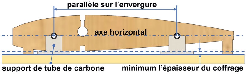
I used Winghelper to design a ribbed airplane, a replica of a Multiplex Capriolo, a small trainer from the 1980s. Important detail: I had the software align the ribs with the underside of the wing so that the rib bases would be parallel to the work surface. I added rib supports at the front and rear. I then planned to run two equidistant carbon (or other material) spars, each 5 mm in diameter, through the ribs to serve as construction aids.
Challenge: the two carbon tubes must be parallel to the work plane. This is easier to achieve with design software than with Winghelper! In fact, Winghelper places its holes on the profile’s centerline at equal distances from the upper and lower surfaces.
The 3-mm ribs are then laser-cut.
Step 2
Draw a “carbon tube” bracket with a length exactly equal to the distance between the ribs. The holes visible in the photos of the brackets were designed to screw the bracket onto the worktable or to secure the tubes. I ultimately glued these brackets to the worktable, placing adhesive tape between them so that I could later remove the brackets without damaging the table. You need to print (here in
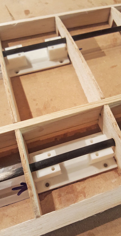
Carbon tube support.
(PLA) Print at least 4 supports and position them precisely (perpendicularity!) on the build plate. The exact positioning of the ribs will be achieved using the “comb,” which serves as a spacer between the two spars. This is generated by Winghelper and is cut out along with the ribs.
Step 3
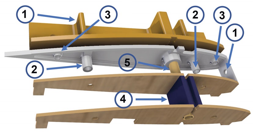
To continue the exercise, I designed a PLA root rib (3) in Fusion 360 that incorporates the two structural tubes (2), the wing spar (5), two centering pins (opposite (2)), two magnets (3), and the positioning pins. I even made a jig to position the rib (1): a lot of work, but unnecessary, given how precise the assembly is. I also made a spacer to position and hold the wing spar tube (4). The challenge for a beginner is incorporating all the angles related to the wing’s dihedral and sweep into the drawings, but it’s an excellent exercise!
Step 4
Now it's time to assemble the entire wing structure, which is a breeze. The exact positioning of the ribs will be achieved using the “comb,” which serves as a spacer between the two spars. This is generated by Winghelper. You can use the same one at the leading edge, but you might as well place it between the spars as spacers.
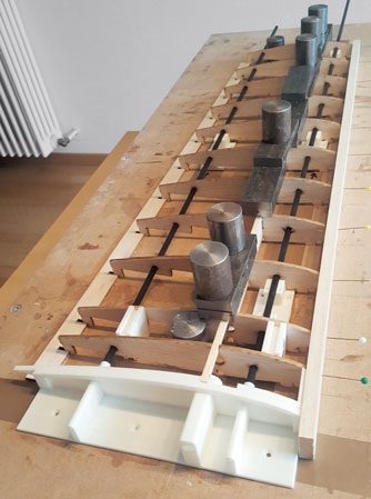
a small circular saw (e.g., Proxxon) to remove the excess tenths. You'll then notice that you can handle your wing structure, remove it from the work surface, and put it back in exactly the same place. The fit is absolutely precise. You’ll be able to continue working on your project right up until the final formwork for the underside is installed.
Step 6
At this stage, you can finish integrating your components—landing gear, wing struts, and servos—sand the leading and trailing edges, and form the upper surface. As usual... The servo mount is also 3D-printed. The upper surface fairing of the wing is glued on at the build site. The carbon tubes are removed
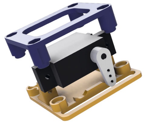
and the holes in the ribs are used to route the servo wires. Then the wing is removed from the work area so that the underside can be formworked.
Construction aids have become indispensable to me for both the enjoyment and precision of the building process. The weight of the 3D structural components (ner-
wing root struts and wing tip struts) quickly becomes significant. These parts should be used sparingly! It doesn’t make sense to build a lightweight balsa frame only to weigh it down with unnecessary parts.
This is a construction principle intended to give you ideas that everyone can adapt to their own style.


News from HEBU

TEAM MANAGER "THIS" BOSSHARD
 Rodito Nussbaumer

SUMMER FUN 2026 AT MG USTER
Martin Wunderli
TRY-OUT DAY AT MFV WETTINGEN
Urs Keller
52. 2026 ALPS CUP
 Emil Giezendanner

ATOM, THE NEW DOUBLE-DECKER FROM CPLR
 Matthias Bosshard

INSIGHTS INTO THE HISTORY OF SEAPLANES

YOU KNOW WHAT I MEAN? 125 YEARS OF THE SWISS AERO CLUB
Emil Giezendanner
34th HAHNENMOOS ALPINE MODEL AIRPLANE CAMP
Res Dauwalder
CORSAIR F4U – A WARBIRD WITH A MEMORABLE LOOK
Jürgen Rosenberger, Jürgen Prinz
SMALL, MODEL-LIKE SAILBOATS
Res Dauwalder
F3A EUROPEAN CHAMPIONSHIPS IN ST-MACAIRE, FRANCE
Matthias Bosshard
What's New at Leomotion.com

HORIZON HOBBY/LEMACO NEWS: MICRO OV-10 BRONCO 645 MM BY E-FLITE

PRIDE AND GOOD IDEAS
 Markus Nussbaumer

BY YOUTH, FOR YOUTH
Lorena Betschen
FREE FLIGHT IN THE MIDDLE OF SUMMER
Urs Muntwyler
THE PC-21 STORY
Emil Giezendanner
TWIN TOWN PARTNERSHIP
Wolfgang Voeller
EURO CONTEST GLIDER ACRO TOUR AUSTRIA 2026

WELCOME, NEW MEMBER!
Andrea Bolliger
COUPE DES ALPES – OBSERVE AND LEARN
Rodito Nussbaumer
NEWS FROM HEBU
 Julia Bucher

FROM 0 TO 100
Markus Nussbaumer
MEMORIES
Wolfgang Völler
NOS REGION – A HUB FOR ELECTRIC AVIATION
Emil Giezendanner
Have you almost forgotten about aircraft that take off and land vertically?
Emil Giezendanner
70 YEARS OF THE NIDWALDEN MODEL AIRPLANE CLUB
Martin Barmettler