
Pilatus PC-6 Porter – Model-Building Culture?
While browsing the internet, a photo of the airframe of a 3-meter Pilatus PC-6 Porter from Pichler catches my eye—not an ARF kit, but something to build by hand in my home workshop—and my spontaneous decision: “I’m building this.”
A few days after placing the order, I have the kit for an airplane with a wingspan of 3.175 m and a fuselage length of 2.30 m in front of me. A quick inspection—from the spinner to the linkages, propellers, wheels, and fuel tank for a combustion engine—shows that everything needed is included and of good quality. There should be no need to go through the hassle of buying additional accessories. The frames and ribs are laser-cut to size, packaged by construction stage, and numbered sequentially. You separate the individual parts from the respective sheet using a utility knife along 1-mm-wide tabs and—as the build process demonstrates—fit them neatly into pre-milled frames or slots without any further processing.
A word of criticism regarding the assembly instructions: the process is laid out in detail with photos and brief English commentary. One drawback: the photos are small and printed in faint black and white, making them difficult to make out at times. Here, one would have preferred, for example, line drawings or a CD with color illustrations. A 1:3 scale layout plan is included.
Following the instructions, you first assemble the main spar from two plywood halves using pre-lasered stringers, glue on a reinforcement, and then insert the ribs one by one at right angles. The wingtips and leading edge are slid into pre-milled grooves. In the next step, we insert a front and a rear fiberglass-reinforced plastic (FRP) plug-in tube into circular cutouts while applying thickened resin; thanks to the high precision of the fit, this can be done with almost no force required. Servo frames are glued into place at predetermined locations using the tongue-and-groove principle. Thanks to the rectangular wing shape, the skin panels—which are precisely cut by the manufacturer—can be easily installed. The usual laborious process of adjusting the panels to the leading and trailing edges is eliminated; the high-quality prefabrication of all parts reduces sanding work to a minimum.
In the next step, we turn our attention to the wing flaps—two for the ailerons and two for the landing flaps. Perfectly cut pieces with pre-milled joints facilitate the simultaneous fabrication of a left and right aileron as well as two landing flaps. It’s worth noting that the points where the linkages—consisting of threaded rods—will later be installed are reinforced with custom-cut maple blocks to provide a sturdy anchor. This prevents the control horns from loosening, for example, due to engine vibration.
When building the horizontal stabilizer with damping fin and control surfaces, we attach the ribs at right angles to the milled end strip and insert an upper and lower jaw strip in the center. When applying the pre-cut skin, a conceptual error becomes apparent for the first time
A conceptual error becomes apparent. The upper skin must be applied to a spherical surface—which slopes differently toward the front and to the side—and cannot be glued on in a single piece as planned by the manufacturer, but must instead be applied in two separate sections.
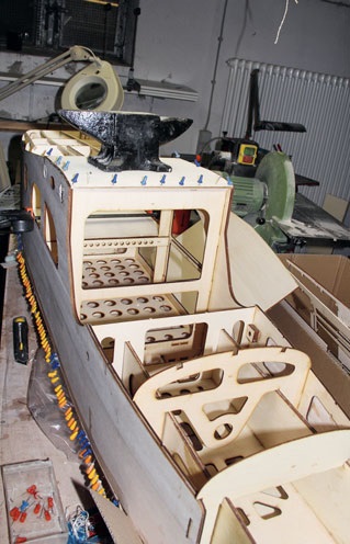
The rudder is constructed using profiled ribs covered with planking on both sides. It is controlled by a servo mounted in the damping fin, while the elevators are controlled via short pushrods extending from the fuselage. When building the fuselage in two parts, we start with the rear half. Place the right side panel on the workbench. Starting from the tail end, glue the frames into the pre-lasered frames, then attach the opposite side panel. After inserting the upper and lower balsa strips, the upper and lower surfaces are planked. The forward fuselage section (built in the same manner) naturally requires more material. The fit is amazing—the workflow is simple: insert, glue, wait, done. There’s virtually no risk of introducing warping, because the pre-cut side panels and the cabin floor—all of which are pre-drilled—determine the alignment of the frames. Next comes the application of the upper and lower planking, as well as embedding the two fiberglass-reinforced plastic (FRP) insertion tubes in resin. Finally, we join the two fuselage halves together; this is when the first round of puttying and sanding begins.
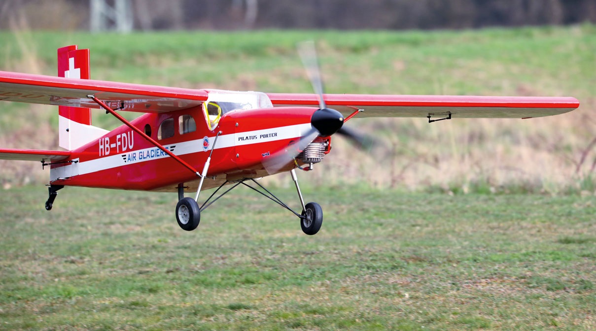
Why did I decide against an electric motor—and thus against the prevailing trend? A 13-kg glider requires a 12-s motor; if you want to complete multiple flights lasting more than 10 minutes—or even tow large gliders—having a large number of batteries is a must. The argument—that we have a gasoline-powered generator running at the edge of the airfield—can’t seriously hold water. To be honest, I have to admit: there’s an “unused” DA 85 sitting on the author’s shelf. An exhaust pipe that looks like it came from a Wilga? No, thanks! The muffler is designed to be hidden inside the fuselage. A set of exhaust bends from Zimmermann/Oeynhausen is fitted and welded together. The bend of the exhaust protrudes about 8 cm from the cowling—not cosmetically objectionable, but beneficial for good cooling. The muffler is located in the passenger compartment; a circular 8-cm hole in the left side door and two rear windows left open ensure airflow. The engine mount—which comes from the manufacturer with a camber and lateral adjustment—can be easily slid into place and secured, and the mounted engine protrudes exactly at the front edge of the hood with its hub. Subsequent balancing, with the center of gravity at 68 mm, proves that the drive concept is well-suited in terms of weight distribution.
Installing the accessories takes just a few minutes—servos are screwed in without any additional work and connected to the linkages via push rods. Only the two-legged landing gear requires a modification. The 3-blade 25.5/12 Elsterprop propeller, which is designed for the DA 85, has insufficient ground clearance. The 120-mm wheels are replaced with 168-mm Fema products. A special feature: The clear windows—pre-cut to fit perfectly—are pressed into the fuselage cutouts and secured with just a few dots of glue, well out of the pilot’s field of view.
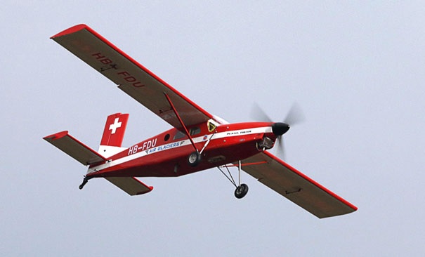
Takeoff is performed at half throttle. The Pilatus lifts off after about 30 meters with a pleasant level of noise. Flying is initially pleasantly trouble-free. At half throttle, the aircraft responds smoothly to all control inputs. After a while, an anomaly becomes apparent. At higher engine RPM, the P-6 yaws to the right without any input from the controls. During a low flyby, we notice what ground checks later confirm: the left aileron servo begins to oscillate at higher engine RPM. The first landing takes place without landing flaps, pleasantly stress-free. The engine power is reduced, the glider glides in with a touch of throttle, and it touches down as smooth as butter. After replacing the aforementioned aileron servo, subsequent takeoffs demonstrate exemplary flight behavior. The DA 85 has sufficient power reserves to launch larger gliders in the 5- to 6-meter class without risk. The motorization proves ideal; no heat buildup is detectable inside the fuselage. The silhouette typical of Pilatus—with its high vertical stabilizer, long nose, and stork-like landing gear—is highly recognizable. You can tell by looking at the model—it has been tried and tested over the long term and wasn’t thrown together hastily.
Conclusion: a complete model kit of exquisite quality with attention to detail and a good price-to-performance ratio. Thanks to high-quality prefabrication combined with precise fit, assembly is frustration-free; everything fits together almost seamlessly, Lego-style. In flight, it’s a docile model that’s also ideally suited for club tow operations. The model-building culture, which had been in danger of falling by the wayside, has been rediscovered!
| Manufacturer | The World Models Manufacturing Co., Ltd. (Made in China), distributed by Pichler |
| Wingspan | 3175 mm |
| Fuselage Length | 2,300 mm |
| Center of gravity | 68 mm behind the leading edge |
| Weight | 12,900 kg |
| Engine | DA 85 with “Zimmermann” manifold and silencer |
| Propeller | 25.5/12 three-blade Elster propeller |
| Fuel Tank | 750 ml |
| Servos | 1× aileron, 2× elevator, 2× rudder, 2× flap, 1× throttle, 1× choke, 1× tow hook >Model Master DS 6040 Titan, Digital, distributed by Pichler |
| Cortex Bavarian Demon gyro |


TEAM MANAGER "THIS" BOSSHARD
 Rodito Nussbaumer

YOU KNOW WHAT I MEAN? 125 YEARS OF THE SWISS AERO CLUB
 Emil Giezendanner

F3A EUROPEAN CHAMPIONSHIPS IN ST-MACAIRE, FRANCE
 Matthias Bosshard

News from HEBU

SUMMER FUN 2026 AT MG USTER
Martin Wunderli
TRY-OUT DAY AT MFV WETTINGEN
Urs Keller
52. 2026 ALPS CUP
Emil Giezendanner
BY YOUTH, FOR YOUTH
Lorena Betschen
ATOM, THE NEW DOUBLE-DECKER FROM CPLR
Matthias Bosshard
CORSAIR F4U – A WARBIRD WITH A MEMORABLE LOOK
Jürgen Rosenberger, Jürgen Prinz
SMALL, MODEL-LIKE SAILBOATS
Res Dauwalder
What's New at Leomotion.com

TWIN TOWN PARTNERSHIP
Wolfgang Voeller
EURO CONTEST GLIDER ACRO TOUR AUSTRIA 2026

INSIGHTS INTO THE HISTORY OF SEAPLANES

34th HAHNENMOOS ALPINE MODEL AIRPLANE CAMP
Res Dauwalder
HORIZON HOBBY/LEMACO NEWS: MICRO OV-10 BRONCO 645 MM BY E-FLITE

COUPE DES ALPES – OBSERVE AND LEARN
Rodito Nussbaumer
PRIDE AND GOOD IDEAS
 Markus Nussbaumer

FREE FLIGHT IN THE MIDDLE OF SUMMER
Urs Muntwyler
THE PC-21 STORY
Emil Giezendanner
WELCOME, NEW MEMBER!
Andrea Bolliger
NEWS FROM HEBU
 Julia Bucher

FROM 0 TO 100
Markus Nussbaumer
MEMORIES
Wolfgang Völler
NOS REGION – A HUB FOR ELECTRIC AVIATION
Emil Giezendanner
Have you almost forgotten about aircraft that take off and land vertically?
Emil Giezendanner
70 YEARS OF THE NIDWALDEN MODEL AIRPLANE CLUB
Martin Barmettler