
Sintered Cells for Model Making
Many model builders who enjoy model aircraft flying as a hobby will have already read or heard that VARTA-Batterie AG, based in Hagen, Westphalia, is offering a new battery cell that is particularly well-suited for electric flight due to its enormous high-current capacity.
This is a further development of the gas-tight nickel-cadmium cell RS 1.2, now designated RSH 1.2. The design of cylindrical nickel-cadmium batteries, the different electrical properties of the two cell types, and—for the sake of completeness—the charging options are described below.
VARTA manufactures gas-tight nickel-cadmium rechargeable batteries in a cylindrical design with sintered electrodes, with capacities ranging from 100 mAh to 7 Ah. With approximately 78 Wh/l and approximately 27 Wh/g, they have the highest energy density and power-to-weight ratio, respectively, of all model series.
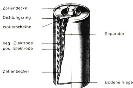
To make optimal use of the cell volume, the electrodes—in the form of a winding made of highly porous sintered tape—are housed in a drawn, nickel-plated steel can. The active material—nickel hydroxide as the positive electrode and cadmium hydroxide as the negative electrode—is impregnated into this highly porous sintered structure. The electrodes are isolated from one another by plastic nonwoven separators. The negative electrode is connected via the nickel-plated steel cup; the positive electrode is connected to the cell lid, which is also made of sheet steel. The cell cup and cell cover are insulated from each other by a plastic ring, which also serves to seal the cell. Potassium hydroxide solution, which is retained within the electrodes and the separator, serves as the electrolyte—the conductor of electricity between the electrodes.
For electric flight, RS 1.2 cells are the preferred choice; they are used in a 7-cell battery pack or as 8-cell batteries divided into 2 units of 4 cells each. The cells, which are insulated with heat-shrink tubing, are arranged in a row and connected using sturdy strip connectors via spot welding.
The battery pack manufactured in this way is fitted with plastic half-shells, which are glued in place or wrapped with tape. Current is conducted via flexible cables.
Cylindrical sintered cells were originally designed for a continuous load of $20 \times I_{10}$ (2 CA), with twice that load permitted for short periods and higher current peaks allowed only for durations in the range of seconds. This results in the following specifications for the RS 1.2 cell:
| Cell Type | RS 1.2 |
| Capacity: 10 standard hours | Ah 1.2 |
| 5 standard hours | Ah 1.2 |
| Discharge current (10 stdg.) | mA 120 |
| 5 stdg. | mA 240 |
| Average discharge voltage (10 hours) | V 1.24 |
| 5 hours | V 1.24 |
| Final discharge voltage (10 hours) | V 1.10 |
| 5 hours | V 1.00 |
| Maximum continuous load | A 2.4 |
| Max. permissible short-term load: | A 4.8 |
| Charging current for 14 hours of charging | mA 120 |
| Charging voltage | V 1.35 to 1.47 V |
| Cell weight | g 65 |
| Cell dimensions in mm | Ø 25.5 h 49 |
It should be noted that as the discharge current increases, the available capacity decreases; for example, by approximately 20% when the load is $20 \times I_{10}$.
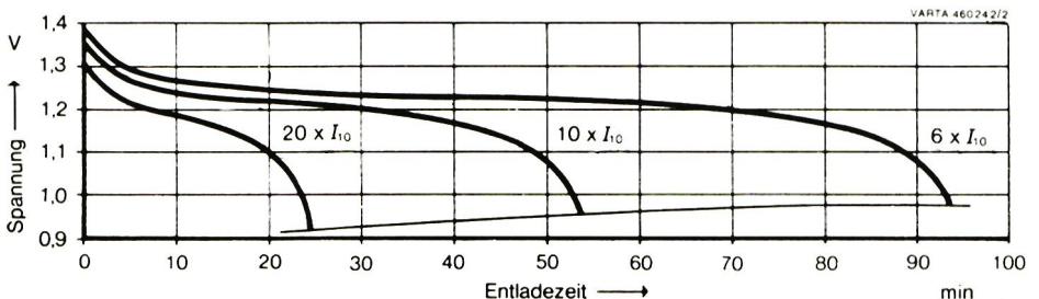
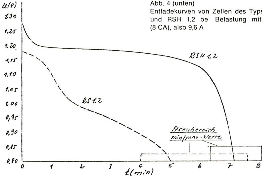
However, since the battery in electric flight is subjected to current loads between 8 A and 12 A—that is, loads between $60 \times I_{10}$ (6 CA) and $100 \times I_{10}$ (10 CA), one inevitably observes very poor voltage performance when using the RS 1.2 cell type. This results in a significant reduction in the available capacity.
For cells capable of handling high currents, these two properties must therefore be improved, and VARTA has succeeded in doing so to an astonishing degree with the design of the RSH 1.2 cell type.
This cell type, which has the same dimensions and nearly the same weight as the RS 1.2 cell, can be continuously loaded at $100 \times I_{10}$ (10 CA) without restriction. Furthermore, even at this maximum load, the RSH 1.2 cell still has an average discharge voltage of approximately 1.15 V and a discharge capacity of approximately 90%.
The different behavior of the two cell types is very clearly evident from the curves shown in Fig. 4 and Fig. 5. It can be seen that the new cell type has an average discharge voltage that is approximately 0.2 V higher and a recoverable capacity that is, on average, approximately 60% higher under high-current loads.
The rise in cell temperature during discharge and charge is also significantly lower, as shown in Fig. 6.
Sealed nickel-cadmium batteries have a charge factor of 1.4, which means they must be charged with 1.4 times the amount of charge that was discharged from the battery. In general, charging should be performed at a constant current. If a slightly declining characteristic curve is used, the specified constant current must be maintained as an average value. The following charging methods are used:
| 14 to 16 h with $I_{10}$ | (0.1 CA) |
| 7 hours with $2 \times I_{10} \hat{=} I_5$ | (0.2 CA) |
| 4.5 to 5 h with $3 \times I_{10}$ | (0.3 CA) |
The charging process can be stopped manually or by a timer. Cylindrical sintered cells can be charged from any state of charge at a maximum current of $3 \times I_{10}$ (0.3 CA), since overcharging at this current is still permitted.
In addition, two different fast-charging methods can be used: voltage-dependent or time-limited after pre-discharge.
In voltage-dependent fast charging, the battery is charged at a current of $10 \times I_{10}$ (1 CA) up to 1.52 V/cell at a temperature of 20°C. The cut-off voltage must be adjusted for higher temperatures using a temperature coefficient of $-4 \text{ mV}/^\circ\text{C}$ to accommodate higher temperatures, so that, for example, the charger shuts off at 1.48 V/cell at 30°C. This method achieves a charge level of 80–90% of the rated capacity.
Time-limited fast charging is easier to implement and is therefore particularly popular among model builders. Before charging begins, the battery is discharged to 1.0 V/cell to prevent significant overcharging. Charging can then be performed with a current of $10 \times I_{10}$ (1 CA) for a total of 60 minutes, or with a current of $20 \times I_{10}$ (2 CA) for a maximum of 30 minutes. Batteries with no more than 7 cells can also be charged using this method from a 12-V car battery. A state of charge of 90 to 95% can be achieved. As an additional safety measure for all charging methods—but especially for fast-charging methods—a temperature switch can be attached to the casing of a cell to interrupt charging when the temperature reaches 50°C.
New batteries should be thoroughly charged before use: 14 hours at $I_{10}$ or 7 hours at $2 \times I_{10}$.
Batteries that have been in storage for more than 6 months should be charged for 24 hours at $I_{10}$ or 12 hours at $2 \times I_{10}$. After a deep discharge—that is, when the voltage falls significantly below the permissible final discharge voltage—the next charging cycle should also be extended by a few hours, e.g., 18 hours at $I_{10}$.
Sealed nickel-cadmium batteries can be stored for several years regardless of their state of charge. Recharging should be performed in the same manner as when putting new batteries into service. The battery will regain its full capacity after 2 to 3 charge/discharge cycles.
Temperature Conditions:- Operation: $-40^\circ\text{C}$ to $+50^\circ\text{C}$;
max. 24 h at $+60^\circ\text{C}$ - Charging: $0^\circ\text{C}$ to $+45^\circ\text{C}$;
recommended: $+10^\circ\text{C}$ to $+35^\circ\text{C}$ - Storage: $-40^\circ\text{C}$ to $+50^\circ\text{C}$,
max. 24 h up to $+60^\circ\text{C}$; $0^\circ\text{C}$ to $+45^\circ\text{C}$ is
recommended
The RS 1.2 cell type describes the construction, electrical specifications, performance, and charging characteristics of cylindrical sintered cells. In parallel, the newly developed RSH 1.2—which is particularly well-suited for high-current applications—is compared.
It is worth noting in this context that VARTA will be introducing further new developments, with the next one expected to be the 750 mAh (750 RS) cell type under the new model designation 750 RSH. At the end of this document, you will find the most important handling instructions for users.


News from HEBU

TEAM MANAGER "THIS" BOSSHARD
 Rodito Nussbaumer

YOU KNOW WHAT I MEAN? 125 YEARS OF THE SWISS AERO CLUB
 Emil Giezendanner

F3A EUROPEAN CHAMPIONSHIPS IN ST-MACAIRE, FRANCE
 Matthias Bosshard

52. 2026 ALPS CUP
Emil Giezendanner
PRIDE AND GOOD IDEAS
 Markus Nussbaumer

ATOM, THE NEW DOUBLE-DECKER FROM CPLR
Matthias Bosshard
CORSAIR F4U – A WARBIRD WITH A MEMORABLE LOOK
Jürgen Rosenberger, Jürgen Prinz
SUMMER FUN 2026 AT MG USTER
Martin Wunderli
TRY-OUT DAY AT MFV WETTINGEN
Urs Keller
TWIN TOWN PARTNERSHIP
Wolfgang Voeller
BY YOUTH, FOR YOUTH
Lorena Betschen
SMALL, MODEL-LIKE SAILBOATS
Res Dauwalder
What's New at Leomotion.com

HORIZON HOBBY/LEMACO NEWS: MICRO OV-10 BRONCO 645 MM BY E-FLITE

COUPE DES ALPES – OBSERVE AND LEARN
Rodito Nussbaumer
EURO CONTEST GLIDER ACRO TOUR AUSTRIA 2026

INSIGHTS INTO THE HISTORY OF SEAPLANES

34th HAHNENMOOS ALPINE MODEL AIRPLANE CAMP
Res Dauwalder
WELCOME, NEW MEMBER!
Andrea Bolliger
FREE FLIGHT IN THE MIDDLE OF SUMMER
Urs Muntwyler
THE PC-21 STORY
Emil Giezendanner
NEWS FROM HEBU
 Julia Bucher

FROM 0 TO 100
Markus Nussbaumer
MEMORIES
Wolfgang Völler
NOS REGION – A HUB FOR ELECTRIC AVIATION
Emil Giezendanner
Have you almost forgotten about aircraft that take off and land vertically?
Emil Giezendanner
DO YOU KNOW WHAT I MEAN IN THE LAND OF SMILES?
Emil Giezendanner