
Diana 2 – a special and one-of-a-kind aircraft
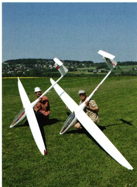
In *Modellflugsport* No. 3/2005, the author reported on the replica of the Polish racing-class glider Diana 1. The article concluded by noting that the team of Richi Oberholzer and Georg Staub was considering building a model of the successor, the Diana 2, as well. In the meantime, two of these new gliders—built on a 1:3 scale—have completed their test phase.
The Diana 2 is largely based on the experience gained with the Diana 1. Let’s therefore begin with a few remarks about the Diana 1. Bogumil Beres, head of the design team at the Polish company SZD, had set himself the goal in the late 1980s of breaking new ground without compromise in the 15-meter racing class. The result of this development work was the Diana 1, a rather unusual glider. With a thickness of 13% at the wing root, it had the thinnest airfoil profile, the highest aspect ratio (27.6) of any racing-class glider, and the smallest combined fuselage and wing area. With an empty weight of just 187 kg, the Diana 1 was a true lightweight, weighing about 50 kg less than its competitors—
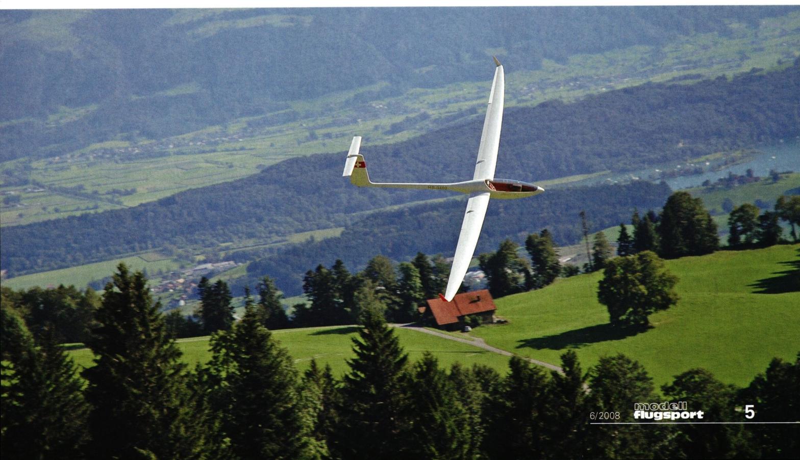
currents. Another significant weight reduction resulted from the highly unusual decision to forgo a wing spar. All bending, shear, and torsional forces were absorbed by the wing skins. In addition to its extremely slender silhouette, the uncompromising use of carbon and aramid fibers also contributed to its low weight. The wings held 160 liters of water ballast, giving the Diana 1 the best ratio of empty weight to ballast capacity. The wings, which featured three flaps for camber and aileron control as well as dive brakes, were—another unique design feature—mounted by being slotted onto a short spar protruding from the fuselage. No sooner had the first Diana 1 completed its maiden flight in 1990 than various top pilots successfully used it to set records. An initial series of women’s records was followed by additional speed records over 300-, 500-, and 1,000-kilometer triangles. In the process, they managed to fly a 1,000-kilometer triangle at a phenomenal average speed of 144.95 km/h. In Poland, a local pilot even won the Polish Championship in the Open Class when he competed against the “Super Orchids” in the racing-class Diana 1. Bogumil Beres, who had acquired the rights to the Diana 1 after SZD went bankrupt, produced a few units in his workshop. Commercially, the Diana 1 was not a success. Although not difficult to fly, it remained an aircraft for a select few success-oriented and uncompromising pilots who had made maximum performance their sole priority.
Even while the Diana 1 was still in production, Bogumil Beres was already working on the design of the Diana 2. Thanks to access to state-of-the-art computers and software, and the collaboration of an aerodynamics expert from the Warsaw University of Technology, a completely new wing with a new airfoil profile was developed. Whereas the Diana 1 still featured the classic multi-trapezoidal configuration with a straight leading edge throughout, the Diana 2’s wing is now strongly elliptical and swept back. This reduces both induced drag and profile drag. At 12.8% at the root and 12.2% at the wingtip, the Diana 2’s wing profile is even slightly thinner than that of the Diana 1. Thanks to the completely new layout, the wing area has increased by 0.48 m², while the aspect ratio has been slightly reduced. The wing’s construction, which is manufactured in CNC-milled molds, remains the same as that of the Diana 1—that is, a pure monocoque design. However, the flaps are no longer segmented and extend across the entire wingspan. The winglets are now standard equipment. Thanks to the slightly lower wing profile, there is more internal space in the wing—which remains sparless—allowing for the carrying of up to 240 liters of water ballast. As a result, the maximum ballast significantly exceeds the further reduced empty weight of 182 kg—a truly unique figure. The Diana 2 is the only glider capable of carrying more water ballast than it weighs when empty. This allows the wing loading to be varied to an unprecedented degree and perfectly adjusted to any weather condition. The fuselage has remained the same, apart from a slightly deeper and lower-drag connecting rib. However, only a long canopy is now offered. With the Diana 1, there was still a choice between a shorter and a longer canopy. The Diana 2 is also controlled with a right-hand sidestick. On January 12, 2005, the Diana 2 took off on its maiden flight. After landing, the enthusiastic test pilot spontaneously declared that he had just flown a Ferrari. That same year, the Diana 2 was entered into competitions and has been striking fear into the hearts of the competition ever since. Already at its first competition in France, it took first place, marking the beginning of an incredible string of victories at numerous European championships. In the World Grand Prix—a new format in gliding competition—the Diana 2 also took first place several times, most recently in 2007 in New Zealand.
Despite its design, which is consistently geared toward peak performance, it is easy to take off, fly, and land—except during the initial phase when heavily loaded. It is noted for its docile low-speed flight characteristics, high agility, and harmonious control surface balance.
While we had chosen a 1:3.5 scale for the Diana 1 to keep the size small and thereby minimize the risk of damage when landing on a slope, we decided—based on our positive experience—to build the Diana 2 on a 1:3 scale. Thanks to original documentation kindly provided by Bogumil Beres, we had a solid foundation for a faithful replica. Once again, as with our earlier projects, consistent use of lightweight construction was the order of the day. With a wing area of 94 dm² and a minimum weight of 6,700 g, this resulted in a minimum wing loading of just 71 g/dm², which turned out to be rather too low during flight testing. For this reason, the Diana 2 is often flown with one kilogram or more of ballast. This raises the legitimate question of whether it makes sense to build a model glider as light as possible only to make it heavier again with ballast. Well, it does make sense, because the mass is located exactly where it should ideally be—namely, at the center of gravity. The glider gains dynamism but, because the wings remain light, loses none of its agility and can be precisely controlled with minimal control surface deflections, even with a heavy ballast load.
While the model is generally very faithful to the original, we made changes only to the wing flaps. We divided the original’s continuous camber/aileron flap—which runs the entire length of the wing—into three individually actuated segments. In addition, we omitted the dive brake, since model gliders with six-flap wings can be landed perfectly in the “butterfly” position without an additional brake flap—an experience we had gained, among other things, with the Diana 1.
Once again, the tried-and-true HN-474 profile, which has a camber of 2.1%, was used. Norbert Habe—to whom we extend our sincere thanks for his efforts—had, upon request, suggested the HN-930 profile, with a camber of 2.05%, which, in his estimation, is even more forgiving. However, based on our very positive experiences to date, we ultimately decided once again on the HN-474. The approach of using a “naturally fast,” i.e., a slightly cambered airfoil, by increasing its camber via a positive flap setting—and thereby slowing it down—seems to work more successfully than the attempt to reduce the camber of a “naturally slow,” i.e., more strongly cambered airfoil, via a negative flap setting and thereby make it faster. A prerequisite, however, is a low flight mass; otherwise, a slightly curved airfoil will struggle at minimum speed due to the high wing loading. As always, we kept the airfoil thicknesses as thin as possible. The decisive factor was that the existing wing spar at the root and thin 10-mm servos for the outer flaps had to just barely fit. This resulted in a profile thickness of 11% at the root and 9% at the wing tip.
Once again, it was Richi Oberholzer who built the hull mold by sanding down hard foam segments—which he had glued onto a central aluminum tube—with great artistic flair and then covering the shape with fiberglass cloth. This was followed by numerous rounds of filling and intermediate sanding until the surface was smooth. Next came the construction of the hull mold, a task for which Willi Fahrni and Hans Rudolf Lüdi (Lümo) once again came to our aid. The fuselages consist of a sprayed topcoat of UP-Vorgelat and several layers of fiberglass (160 g/m² and 280 g/m²), which are oriented at 90°/0°, 45°, or as unidirectional tape. The challenge was to manage the torsional and bending forces of the very long tailplane spar. A fuselage of this type weighs around 1,500 g, which is a good figure given the scale. A unique feature is the very lightweight retractable landing gear, developed and built by Theo Stähli, which is attached to a single frame with damping silent blocks and suspended by rubber rings. The very long clear canopy was formed by Bruno Greuter.
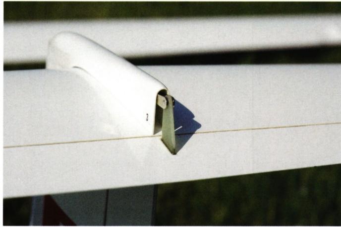
I was responsible for designing the wings and tail surfaces. The real challenge was manufacturing the wing with its elliptical outline using a positive-mold construction method. Since the initial goal was to build two prototypes and we lacked access to a large CNC milling machine for producing wing molds, the only option was to use a Styrofoam construction method. Since the goal was to achieve the highest possible airfoil accuracy, the wing core—especially in the outermost third—had to be assembled from many short Styrofoam segments, 15 in total per wing. The wing core is covered with thin abachi wood. Torsional stiffness is ensured by a D-box, with 160 g/m² carbon fabric used in the inner two-thirds of the wing and 90 g/m² in the outer third. The fiber orientation naturally runs at a 45° angle to the spar. All wing flaps are also backed with 90 g/m² carbon fabric. The spar consists of a Rohacell core encased in a carbon braided tube. The spar transitions seamlessly into the aramid-made mounting pockets, into which the carbon wing connector—molded in a single piece—is inserted. The bending forces are absorbed by spar straps, which are made of individual carbon rovings applied wet-on-wet during the wing bonding process. The number of rovings decreases continuously from the root to the wing tip. Approximately 70 running meters of rovings were used per wing. Two aluminum pins protrude from each wing root, which engage with mounting tubes in the fuselage. Great finesse and precise control using profile-nose templates were essential during the sanding of the wing. This was followed by the construction of the plug-in winglets. After applying a layer of 49 g/m² fiberglass cloth laid diagonally and a subsequent coat of primer, Andi Schwerzmann skillfully sprayed a thin yet opaque two-component paint finish onto the wings, tail surfaces, and fuselage, which were then sanded and polished to a high gloss. Only then were the flaps cut off, reattached with silicone hinges, and the servos installed. When ready to fly, each wing weighs about 1,300 g.
The rudder and horizontal stabilizer are constructed in the same manner as the wings, though without a spar. Given the very long tailplane lever arm, extreme care was taken to minimize weight. On the Diana 2 as well, the horizontal stabilizer sits on the rear half of the rudder damping mechanism—that is, extremely far back—which is why the mounting and flap actuation had to be planned and built with great care.
We also use only a 10-channel receiver for the Diana 2. Since we control the vario and the tow hook via a single receiver output, this number of channels is sufficient. Three flaps positions have been programmed, which are selected via a three-position switch. In the high-speed and slow-flight positions, all three flaps are engaged, but with decreasing outward deflections. When circling in thermals, only the outermost flap functions as an aileron. During takeoff and when flying on a slope, the middle flap is engaged as an aileron, but with reduced deflection. The “crow” position quickly reduces speed significantly, which is why elevator input is added to prevent the glider from stalling.
The Diana 2 truly lives up to its name. It exhibits impressive dynamics, especially when weighted. The speed range tested so far is between 30 and 250 km/h. If you bring the Diana 2 down from 300 m with the flaps in the negative position and race it low over the runway, it’s almost silent. The subsequent climb seems endless. The glider performs huge loops, and the rolls come off like clockwork. With an EWD of just around one degree, the Diana 2 is optimized for high-speed flight. So far, it has been flown with a maximum of 2,700 g of ballast (102 g/dm²), but judging by its slow-flight characteristics with ballast, it could handle even more payload. In terms of structural strength, the payload is not a problem, as the Diana 2 is designed to withstand a load of 25 g. Since the elevator travel has been reduced even further, the Diana 2 circles at a constant, astonishingly slow airspeed without any tendency to tip over. All aileron deflections are small, but the rudder must be consistently deflected in the direction of the turn; otherwise, the Diana 2 will “get stuck” in a circle. This is where its high course stability comes into play, allowing the Diana 2 to glide in a straight line as if on rails. The V-shape, at just 2.5 degrees per side, is at the lower limit. However, combined with the strong sweep—which also has a stabilizing effect during turns—the slight V-shape is sufficient. The low-mounted wing structure requires increased attention during takeoff and landing on runways that haven’t been freshly mowed, due to the small ground clearance of the wingtips. On approach, the Diana 2 glides as if on rails. With the flaps set to a positive angle, the final approach is slow and stable; excess altitude is efficiently reduced using the “butterfly” position without increasing airspeed.
The Diana 2 is a very special and unique aircraft. Both on the ground and in flight, its graceful silhouette immediately sets it apart from other gliders. It is a sheer delight to fly, whether in thermals or on a slope. Its dynamics seem limitless. Every flight rewards us anew for the many hundreds of hours we’ve invested in the development and construction of the Diana 2.


TEAM MANAGER "THIS" BOSSHARD
 Rodito Nussbaumer

YOU KNOW WHAT I MEAN? 125 YEARS OF THE SWISS AERO CLUB
 Emil Giezendanner

F3A EUROPEAN CHAMPIONSHIPS IN ST-MACAIRE, FRANCE
 Matthias Bosshard

News from HEBU

SUMMER FUN 2026 AT MG USTER
Martin Wunderli
TRY-OUT DAY AT MFV WETTINGEN
Urs Keller
52. 2026 ALPS CUP
Emil Giezendanner
BY YOUTH, FOR YOUTH
Lorena Betschen
ATOM, THE NEW DOUBLE-DECKER FROM CPLR
Matthias Bosshard
CORSAIR F4U – A WARBIRD WITH A MEMORABLE LOOK
Jürgen Rosenberger, Jürgen Prinz
SMALL, MODEL-LIKE SAILBOATS
Res Dauwalder
What's New at Leomotion.com

TWIN TOWN PARTNERSHIP
Wolfgang Voeller
EURO CONTEST GLIDER ACRO TOUR AUSTRIA 2026

INSIGHTS INTO THE HISTORY OF SEAPLANES

34th HAHNENMOOS ALPINE MODEL AIRPLANE CAMP
Res Dauwalder
HORIZON HOBBY/LEMACO NEWS: MICRO OV-10 BRONCO 645 MM BY E-FLITE

COUPE DES ALPES – OBSERVE AND LEARN
Rodito Nussbaumer
PRIDE AND GOOD IDEAS
 Markus Nussbaumer

FREE FLIGHT IN THE MIDDLE OF SUMMER
Urs Muntwyler
THE PC-21 STORY
Emil Giezendanner
WELCOME, NEW MEMBER!
Andrea Bolliger
NEWS FROM HEBU
 Julia Bucher

FROM 0 TO 100
Markus Nussbaumer
MEMORIES
Wolfgang Völler
NOS REGION – A HUB FOR ELECTRIC AVIATION
Emil Giezendanner
Have you almost forgotten about aircraft that take off and land vertically?
Emil Giezendanner
70 YEARS OF THE NIDWALDEN MODEL AIRPLANE CLUB
Martin Barmettler