
Elevator rail for drive belt
Rubber-powered models are a fascinating aspect of our hobby. It doesn’t matter whether they belong to one of the FAI classes (F1B, F1D, Coupe d’Hiver) or another class (Peanut, Walnut, Kit-Scale, Jumbo-Scale, P30, etc.).
What they all have in common is a propulsion system using rubber bands, which must be wound once they’re secured in the model. There are various methods for doing this, as shown in Figures 1 through 5.
With all of these methods, there’s always the risk of damage or even destruction of the model if a rubber cord snaps. This is true even with proper preparation of the rubber cords—stretching, lubricating, and adjusting the number of turns. Rubber cords are, after all, consumables.
I’ve been thinking about how I can avoid this risk by winding the drive train outside the model and then inserting and securing it inside the model once it’s fully wound.
The solution I’ve been using for years: a tensioning rail made from an aluminum U-channel. Corresponding to the usable
fuselage length, the aluminum profile (available in various sizes at hardware stores) is cut to length with a bit of extra length and notched at both ends. These notches are later widened to accommodate the spool and locking pin. The extra length is necessary because a stop is glued to the rail.
The unpanned fuselage, ready for the airframe, is prepared. The intended anchor made from a round bar is replaced with a brass or aluminum tube. A piece is cut from this and machined to match the clear width of the U-channel (Figure 6).
The remaining piece is split into two parts. The three parts are threaded onto a kebab skewer and inserted into the holes in the fuselage reinforcements. Now the aluminum rail is inserted and secured in a vise. The fuselage now hangs from the rail, and the stop at the fuselage nose can be glued to the rail. ■
More pictures on the next spread →
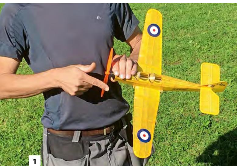
1 By hand.
2 With an assistant and a winch.
3 With the model secured in the lifting block and a winch.
4 As in Figure 3, but with a protective tube over the rubber.
5 Secured by the feet and pulled taut with a winch.
6 The side pieces, cut to length and machined as needed, are glued into the holes in the reinforcements (Figure 8).
7 Before securing the rubber, a guide for the aluminum rail is made from scrap wood. Preferably attached to a rib (Figure 9).
8 The previously prepared drive line is fitted with the spool and the hook at its ends, and both parts are secured with dental rubber bands. Clamp the rail in the vise, hook the spool in, and tension the line (Figure 10).
9 The hook has two holes. The locking pin is inserted into one of them to prevent the rubber band from unwinding; the propeller is attached to the other (Figure 11).
10 The unit prepared in this way is inserted into the fuselage as far as it will go. The guide ensures that the spool is in the correct position (Figure 12).
11 The drive train is now secured in the model with a locking pin (Figure 13).
12 Hook the propeller in place, remove the locking pin, and pull the guide rail out of the fuselage (Figure 14).
13 The fuselage nose with the propeller is pulled into the correct position by the tension of the rubber band, and the model is ready to take to the skies (Figures 15 and 16).
14 I use this method for most of my models that have a suitable fuselage cross-section, regardless of how large or small they are—whether they’re utility models or scale models. Damaged or destroyed fuselages have been a thing of the past ever since. Figure 17 shows all the components again.


TEAM MANAGER "THIS" BOSSHARD
 Rodito Nussbaumer

F3A EUROPEAN CHAMPIONSHIPS IN ST-MACAIRE, FRANCE
 Matthias Bosshard

News from HEBU

YOU KNOW WHAT I MEAN? 125 YEARS OF THE SWISS AERO CLUB
 Emil Giezendanner

SUMMER FUN 2026 AT MG USTER
Martin Wunderli
TRY-OUT DAY AT MFV WETTINGEN
Urs Keller
52. 2026 ALPS CUP
Emil Giezendanner
BY YOUTH, FOR YOUTH
Lorena Betschen
CORSAIR F4U – A WARBIRD WITH A MEMORABLE LOOK
Jürgen Rosenberger, Jürgen Prinz
SMALL, MODEL-LIKE SAILBOATS
Res Dauwalder
What's New at Leomotion.com

ATOM, THE NEW DOUBLE-DECKER FROM CPLR
Matthias Bosshard
INSIGHTS INTO THE HISTORY OF SEAPLANES

34th HAHNENMOOS ALPINE MODEL AIRPLANE CAMP
Res Dauwalder
HORIZON HOBBY/LEMACO NEWS: MICRO OV-10 BRONCO 645 MM BY E-FLITE

COUPE DES ALPES – OBSERVE AND LEARN
Rodito Nussbaumer
PRIDE AND GOOD IDEAS
 Markus Nussbaumer

EURO CONTEST GLIDER ACRO TOUR AUSTRIA 2026

FREE FLIGHT IN THE MIDDLE OF SUMMER
Urs Muntwyler
THE PC-21 STORY
Emil Giezendanner
TWIN TOWN PARTNERSHIP
Wolfgang Voeller
WELCOME, NEW MEMBER!
Andrea Bolliger
NEWS FROM HEBU
 Julia Bucher

FROM 0 TO 100
Markus Nussbaumer
MEMORIES
Wolfgang Völler
NOS REGION – A HUB FOR ELECTRIC AVIATION
Emil Giezendanner
Have you almost forgotten about aircraft that take off and land vertically?
Emil Giezendanner
70 YEARS OF THE NIDWALDEN MODEL AIRPLANE CLUB
Martin Barmettler