
Graupner Electronic PILOT Switch
The Graupner pilot switch is small and lightweight (about the size of a large servo) and replaces mechanical switches operated by servos. It contains two relays with gold contacts for “Off” and “On” as well as for polarity reversal. Unlike electronic switches, relays operate with absolutely no power loss. It’s an unassuming little device, but one that has proven itself excellently in electric flight.
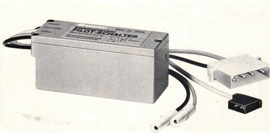
1. Function
This multifunction device allows the electric drive motor to be remotely switched to direction A for propulsion, to “Stop,” and to direction B for thrust reversal. In addition, the drive battery is automatically shut off when the cut-off voltage is reached, thereby protecting it from harmful deep discharge.
The PILOT switch is primarily used with electric propulsion systems featuring a reduction gear and large propellers, as thrust reversal is particularly effective in such configurations.
The PILOT switch is connected to an SC decoder module on the receiver unit using the 3-pin flat plug. The drive motor is connected to the two individual AMP MATE-N-LOK jacks. Caution: To change the specified direction of rotation of the drive motor, swap the two motor connection cables. The drive battery or batteries must not be connected with reversed polarity.
2.1. When using a single battery (e.g., 7/RSH 1.2), only the two outer contacts are used. Observe the polarity (color coding)!
2.2. If two batteries are to be connected in series (e.g., 2 x 4/RSH 1.2), each battery is connected to the outer pair of terminals.
The final discharge voltage depends on the current load and ranges from approximately 0.8 V to 1.0 V per cell.
For high-current loads, where the operating time with a fully charged battery is approximately 10 minutes—for example, when used in electric model airplanes—the value can be assumed to be approximately 0.8 V per cell; for lower loads, the end-of-discharge voltage is correspondingly higher.
The PILOT switch has two adjustment potentiometers for setting the cut-off voltage and the travel. A small screwdriver is used to make the adjustments.
This requires a test run of the electric drive unit installed in the model. To keep the duration of the test run—and thus the load on the electric motor—to a minimum, the drive battery is charged for only about 5 minutes instead of 30 minutes.
During the test run, the drop in voltage is monitored on the meter.
When the final discharge voltage is reached, the potentiometer labeled “shut-off voltage” is turned until the motor stops. The voltage then rises again because the battery is no longer under load.
The motor cannot be restarted after automatic shutdown. The device is not operational again until a charged drive battery is installed.
To check this, the battery must therefore be recharged briefly. During the next test run, the exact cut-off point can then be read on the meter.
The lower limit of the shutdown voltage is approximately 5.5 V. It is therefore advisable to use this device only when the operating voltage is at least 8.4 V but no more than 16.8 V.
5.1. 7-cell VARTA 7/RSH 1.2 battery under high-current discharge: 7 × 0.8 V = 5.6 V.
5.2. Two 4-cell VARTA 4/RSH 1.2 batteries connected in series during high-current discharge: 8 × 0.8 V = 6.4 V.
This is done using the appropriately labeled potentiometer. The activation points for both directions of travel can be adjusted; that is, the drive motor is activated when the control stick on the transmitter is moved to a smaller or larger angle.
In practice, the transmitter’s control stick can be either neutralizing or non-neutralizing:
6.1. Operation with a neutralizing control stick
The unit is factory-set for this function. If readjustment is necessary, it can be done as follows:
It is recommended to adjust the travel so that direction A can be engaged for flight using trim alone. This is important to enable a hand launch of the electric model without operating the control stick. Activating direction B (reverse thrust) is generally not possible using trim alone, but it is also not necessary.
During flight, it is recommended to return the trim to the center position and use the control stick to engage and disengage the reverse thrust. Another advantage of this adjustment method is that the motor cannot start accidentally when the model is parked on the ground, since the neutralizing control stick is always in the center position. However, this requires that the trim be set to neutral as well.
6.1.1. Adjustment with a Neutralizing Control Stick
When the control stick is pushed forward, the motor’s direction of rotation should correspond to A (for flight):
Trim forward; turn the “Travel” potentiometer to the left until the motor starts reliably in the specified direction of rotation.
6.2. Adjustment for a Non-Neutralizing Stick
When the control stick is pushed forward, the engine should rotate in direction A (for flight).
Pushing the stick backward should correspond to engine rotation direction B (for reverse thrust).
Control stick in center position: Engine off.
For the functions described, set the trim to center and the control stick to about two-thirds of its forward travel.
Turn the “Stroke” potentiometer until the engine starts reliably in direction A.
When the control stick is moved backward, the switch point for running direction B is then automatically established.
6.3. Additional Settings for a Non-Neutralizing Control Stick
can be made at your discretion, e.g., for the following function:
Thumbstick forward: motor on, forward
Thumbstick back: Motor off, trim backward, and thumbstick back: Motor reverse on.
7.1. Reverse Thrust on the MOSQUITO and Similar Electric Model Airplanes
The model can be quickly brought back down to ground level from a great height without risk, since thrust reversal acts as a kind of thermal brake. This is particularly advantageous in weather conditions with very strong updrafts. But even in calm weather, the use of thrust reversal is extremely effective.
Thrust reversal is also suitable for making corrections during landing approaches, within certain limits, provided the motor is shut off at a sufficient altitude.
When thrust reversal is engaged, the electric model follows a very steep downward trajectory at a remarkably low airspeed. The model’s controllability remains fully intact.
It is recommended to conduct the first tests with reverse thrust at a higher altitude to become familiar with the model’s behavior. The angle of the flight attitude can be reduced by applying appropriate elevator deflections.
7.2. The PILOT switch is primarily intended for electric model aircraft.
Once the cut-off voltage is reached, the motor can no longer be turned on. The model will glide to the ground.
The motor can only be turned on and off again after connecting a charged battery.
7.3. If the PILOT switch is to be used in the MOSQUITO model, the mechanical switch with plastic mount included in the electric flight set, as well as the servo required to operate this switch, are not needed.
For any electric model aircraft, the battery should only be discharged during flight to the point where the motor can still be used effectively during the landing approach.
If the landing must be aborted for any reason (e.g., people crossing the landing field), there should still be enough power in reserve to go around. If the motor is running weakly, there is a risk of a stall during a go-around. If the pilot switch shuts off automatically when the cut-off voltage is reached, a landing approach can, under certain circumstances, become “dangerous.” Experience shows that the engine requires an enormous amount of power, especially during reverse thrust, so that the cut-off voltage is quickly reached after a longer flight. If the switch cuts off at this point, it is no longer possible to correct a short final approach, etc. Don’t let this catch you by surprise!
| Power supply voltage for the electronics | 4.8 V = |
| Operating voltage | 8.4 ... 16.8 V = corresponds to 7 to 14 NC cells |
| Adjustment range for cut-off voltage | 5.5 ... 12 V = |
| Maximum continuous current limit | 15 A = |
| Weight approx. | 90 g |
| Dimensions approx. | 76 × 28 × 32 mm |
| Cable length approx. | 200 mm |


News from HEBU

TEAM MANAGER "THIS" BOSSHARD
 Rodito Nussbaumer

SUMMER FUN 2026 AT MG USTER
Martin Wunderli
SMALL, MODEL-LIKE SAILBOATS
Res Dauwalder
TRY-OUT DAY AT MFV WETTINGEN
Urs Keller
What's New at Leomotion.com

52. 2026 ALPS CUP
 Emil Giezendanner

BY YOUTH, FOR YOUTH
Lorena Betschen
ATOM, THE NEW DOUBLE-DECKER FROM CPLR
 Matthias Bosshard

INSIGHTS INTO THE HISTORY OF SEAPLANES

YOU KNOW WHAT I MEAN? 125 YEARS OF THE SWISS AERO CLUB
Emil Giezendanner
34th HAHNENMOOS ALPINE MODEL AIRPLANE CAMP
Res Dauwalder
CORSAIR F4U – A WARBIRD WITH A MEMORABLE LOOK
Jürgen Rosenberger, Jürgen Prinz
F3A EUROPEAN CHAMPIONSHIPS IN ST-MACAIRE, FRANCE
Matthias Bosshard
HORIZON HOBBY/LEMACO NEWS: MICRO OV-10 BRONCO 645 MM BY E-FLITE

PRIDE AND GOOD IDEAS
 Markus Nussbaumer

EURO CONTEST GLIDER ACRO TOUR AUSTRIA 2026

FREE FLIGHT IN THE MIDDLE OF SUMMER
Urs Muntwyler
THE PC-21 STORY
Emil Giezendanner
TWIN TOWN PARTNERSHIP
Wolfgang Voeller
WELCOME, NEW MEMBER!
Andrea Bolliger
COUPE DES ALPES – OBSERVE AND LEARN
Rodito Nussbaumer
NEWS FROM HEBU
 Julia Bucher

FROM 0 TO 100
Markus Nussbaumer
MEMORIES
Wolfgang Völler
NOS REGION – A HUB FOR ELECTRIC AVIATION
Emil Giezendanner
Have you almost forgotten about aircraft that take off and land vertically?
Emil Giezendanner
70 YEARS OF THE NIDWALDEN MODEL AIRPLANE CLUB
Martin Barmettler