
The shell wing made from the “disposable mold”
Models with a monocoque construction are considered sophisticated, but they are also complex to manufacture and therefore expensive. In a monocoque wing, the load-bearing structures are concentrated at the very outer edge of the airfoil—in the “skin” of the wing, so to speak—which results in high moments of resistance to tension, compression, buckling, torsion, etc., while maintaining a comparatively low weight.
Monocoque wings, often also called sandwich wings, are typically manufactured in milled or cast negative molds and require significantly more construction effort compared to the classic wooden-rib construction and the wood-planked foam core. The “amateur” model builder—especially if they only want to build a single model—therefore generally steers clear of the monocoque construction method. The following report aims to show that monocoque wings are indeed feasible for amateur model builders with a reasonable amount of effort.
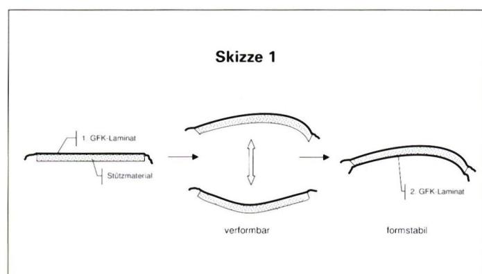
The idea behind this is illustrated in Sketch 1: Single-sided laminated shell support material is still deformable—at least to the extent that wing profiles with standard camber can still be created without difficulty. Only double-sided laminated shell support material retains its shape. The support material (e.g., lightweight balsa, Rohacell, Herex, Depron, aramid honeycomb, etc.) is first laminated on one side under high pressure onto a smooth surface. This laminate then forms the (smooth) outer skin of the shell. Next, the second, inner laminate is applied using a polystyrene positive mold (“stamp”) within a polystyrene negative mold, which is cut using a heating wire according to a tried-and-true method. The surface of the inner laminate is no longer perfectly smooth, but this does not matter.
Sketch 2 schematically shows the step-by-step procedure as I applied it to my second (and most recent) shell wing, the construction of which is documented in the construction stage photos 1–6. The design of this glider wing is not the subject of this report, but here are a few key specifications:
- Wingspan 4.15 m
- Wing depth: 0.25 m (inner), 0.14 m (outer)
- Airfoil: HQ 3.5/12
Applying this technique to this highly curved airfoil best demonstrates that it works: The shells, laminated on both sides, retained their shape perfectly even after prolonged storage.
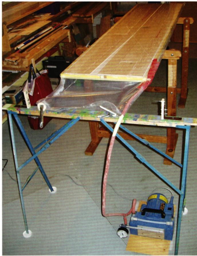
I used a 200×50 cm formboard as a building board, smoothing out the coarser irregularities on one of its surfaces; for the smooth surface material, I used a 0.75-mm PET film from a home improvement store. The 80 g/m² fiberglass cloth for the outer laminate was cut at a 45° angle to achieve better torsional strength, and as a backing material, I used lightweight 2-mm balsa strips, which I had previously glued together to match the wing’s outline with a slight overhang. It is important to prime the backing material on the outside to prevent the resin from penetrating during lamination. Otherwise, the deformability of the support material laminated on the outside would be compromised. With the release film between the PET film and the laminate, you can dispense with the release wax that would otherwise be necessary; however, this film must also be absolutely smooth. So the fabric is placed on the release film, saturated with resin (preferably using a foam roller), the backing material is laid on top, and the whole assembly is cured in a vacuum bag. High pressure during curing is important here to achieve a smooth surface.
After curing, the end edge must be ground to a sharp point so that the shells form a clean end edge when joined together (→ Step 6). The angle of this grinding is critical and must be determined in advance by drawing it on the profile and maintained during grinding; otherwise, profile inaccuracies are to be expected. Since I had planned a spar structure with spars made of carbon fiber tape, I also milled a recess into the support material at this stage, matching the intended tape thickness of approximately 0.5 mm. In accordance with the intended web width, the milled recess tapers from 25 mm at the root to 10 mm at the edge curve. This results in four single-sided coated shells that are identical except for their mirror-image orientation.
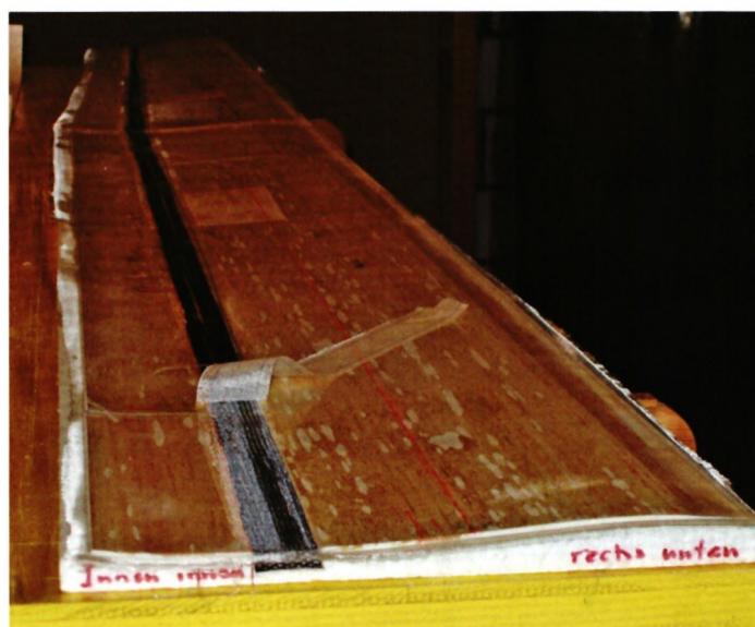
Now, the single-sided laminated shell (the illustration shows the production of the lower shell) is placed precisely into the Styrofoam negative mold and lightly secured, for example, with double-sided tape. The milled recess in the support material is thoroughly coated with slightly thickened resin; the prefabricated stringers are inserted and secured with 2 or 3 pins, whose heads are trimmed almost flush with the surface using pliers. Next, the glass fabric for the inner laminate (here 50 g/m², cut at right angles) is laid on top and saturated with resin, again using the foam roller. On top of that, in the area of the spar straps, I placed a tear-off fabric tape to ensure an optimally rough surface for the subsequent gluing of the spar web. Next, the generously cut release film is placed on top, followed by the foam (approx. 2 cm thick, soft grade), the positive and negative molds (secured against slipping with double-sided tape), and finally one or more flat boards. Using screw clamps, apply enough pressure so that the foam is compressed for the most part, but not completely. This prevents excessive pressure, which would deform the Styrofoam mold.
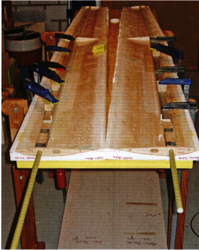
The same procedure is followed for the upper shells. The pressure applied using this “foam molding process” proved to be sufficient to force the shell into even the tighter radii of the top surface of the profile. The positive mold made of Styrofoam can now be discarded; it will no longer be needed in the subsequent steps.
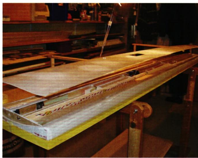
After curing and demolding, the next step is to install components such as the spar (in this case, a glass-tubing-laminated Styrofoam core) with its slot, components for the aileron, speed brakes, plywood ribs at the wing root, along the leading edge, and in this particular case also at the bend in the nose spar (double-trapezoidal geometry), etc.
These inserts were placed in the upper shell primarily because of the air brakes, but this is not mandatory. It’s important not to forget to sand the inner laminate thoroughly in all areas where no tear-off fabric was applied before gluing. All components, except for the spar web—which is slightly undersized in height (the gap will be filled with resin and micro-balloons when the shells are later joined)—are sanded down to the profile height using a long, sturdy sanding block (I used a 1.8-meter-long mason’s straightedge with sandpaper taped to it) down to the profile height. The plywood ribs at the wing root, at the wingtip, and—in my case—also at the wing bend serve as guide ribs. I installed the lightweight support spar in the long, slightly curved rear section of the airfoil because I still didn’t quite trust the dimensional stability of the shells. However, my skepticism was unfounded; the dimensional stability of the shell with the 2-mm balsa support material proved to be excellent.
The two shells are joined together after coating all contact points with thickened resin. In this case, I preferred to use micro-balloons as a thickening agent, since they make it easy to see how much resin has already been applied and where. However, the mixture must still be spreadable with a brush; under no circumstances should it have the consistency of body filler. Since the spar is slightly undersized in height, a relatively large amount of resin is needed here. You should measure the undersize and use that to determine the approximate amount of thickened resin required, which is then applied with a large syringe. A slight excess of resin—which will be squeezed out at the front and back of the stringer when the shells are pressed together—is necessary here and, unfortunately, unavoidable.
The lower shell must now be positioned precisely on the first try so that no further adjustment is needed, which would result in smearing of the applied resin. Here, too, it is important to secure it—for example, with adhesive tape—against the lower shell. Next, place a release film (PE) along the end edges to prevent the mold from sticking due to resin seeping out at the ends, followed by the lower Styrofoam mold negative, which must fit precisely (otherwise, profile inaccuracies will accumulate). Next, place a board, a layer of foam as in Step 3, and another board on top, and again use screw clamps to apply just enough pressure to partially—but not completely—compress the foam, thereby preventing deformation of the mold and, consequently, the wing shells. This step requires working quickly, as there is quite a bit to do within the available pot life (90 min) of the Type L epoxy resin I used—which, by the way, I applied to the entire wing.
After curing, the next steps are to sand down the excess material on the leading edge of the profile down to the end strip, followed by gluing and sanding to profile (use templates!) of the balsa nose edge with an embedded plywood strip (to prevent dents, e.g., from landing impacts), attaching the root cover rib and wing tip, cutting out the ailerons, etc., etc. In this case, the entire wing was also covered with film (using a hair dryer), since the 80 g/m² fiberglass surface, although appearing “smooth” to the naked eye, showed pores between the fiberglass strands that were visible under a magnifying glass. Anyone wishing to avoid this will need to use Vorgelat when laminating the outer layers of the airfoil. The negative molds, which also served as supports throughout the entire construction phase, can now be discarded.
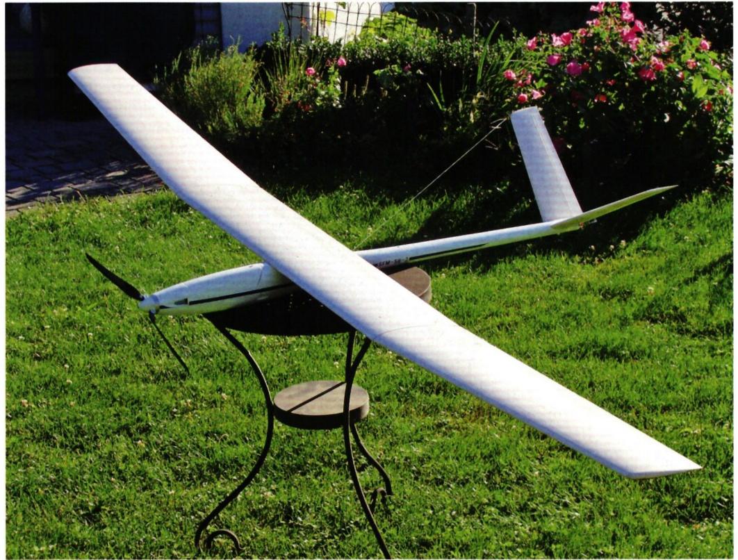
The monoplane wing shown here weighs 2.015 kg when ready to fly, excluding connectors. It’s certainly not a lightweight, but it’s acceptable given the model’s intended total weight of 4.4 kg. The tailplane was built in the same way; the construction of the
You can find these and other instructions at www.modellflugsport.ch
fuselage—by converting/renovating an older fiberglass fuselage using a positive seamless construction method—is still ahead of me. I still see room for improvement in using rigid foam instead of Styrofoam for the mold, which should result in significantly reduced susceptibility to deformation. However, I don’t want to gloss over a weakness of the construction method shown here, namely the construction of the nose strip: The attached balsa nose strip requires very careful sanding by hand. Even a small lapse in attention here can quickly lead to an inaccuracy in the profile! Perhaps one of the readers might find a better solution to this problem?
Bernhard Schönenberger,
MFG Falknis


TEAM MANAGER "THIS" BOSSHARD
 Rodito Nussbaumer

ATOM, THE NEW DOUBLE-DECKER FROM CPLR
 Matthias Bosshard

INSIGHTS INTO THE HISTORY OF SEAPLANES

CORSAIR F4U – A WARBIRD WITH A MEMORABLE LOOK
Jürgen Rosenberger, Jürgen Prinz
SUMMER FUN 2026 AT MG USTER
Martin Wunderli
F3A EUROPEAN CHAMPIONSHIPS IN ST-MACAIRE, FRANCE
Matthias Bosshard
What's New at Leomotion.com

HORIZON HOBBY/LEMACO NEWS: MICRO OV-10 BRONCO 645 MM BY E-FLITE

PRIDE AND GOOD IDEAS
 Markus Nussbaumer

News from HEBU

YOU KNOW WHAT I MEAN? 125 YEARS OF THE SWISS AERO CLUB
 Emil Giezendanner

34th HAHNENMOOS ALPINE MODEL AIRPLANE CAMP
Res Dauwalder
SMALL, MODEL-LIKE SAILBOATS
Res Dauwalder
TRY-OUT DAY AT MFV WETTINGEN
Urs Keller
52. 2026 ALPS CUP
Emil Giezendanner
TWIN TOWN PARTNERSHIP
Wolfgang Voeller
EURO CONTEST GLIDER ACRO TOUR AUSTRIA 2026

BY YOUTH, FOR YOUTH
Lorena Betschen
WELCOME, NEW MEMBER!
Andrea Bolliger
FREE FLIGHT IN THE MIDDLE OF SUMMER
Urs Muntwyler
THE PC-21 STORY
Emil Giezendanner
COUPE DES ALPES – OBSERVE AND LEARN
Rodito Nussbaumer
NEWS FROM HEBU
 Julia Bucher

FROM 0 TO 100
Markus Nussbaumer
NOS REGION – A HUB FOR ELECTRIC AVIATION
Emil Giezendanner
MEMORIES
Wolfgang Völler
Have you almost forgotten about aircraft that take off and land vertically?
Emil Giezendanner
70 YEARS OF THE NIDWALDEN MODEL AIRPLANE CLUB
Martin Barmettler