
Thermoformed propellers for electric model aircraft
Spinners with pre-cut slots for two-blade propellers come in almost every shape, color, material, and size. However, if you’re looking for a spinner with a 69-mm diameter for a three-bladed propeller—one that’s also lightweight and cheaper than a Chinese RTF toy airplane complete with an RC system—the search can go on forever.
What a stroke of luck—perfect conditions and plenty of motivation for a DIY project! While internal combustion engines place quite high demands on a spinner (high resistance to temperature and vibration, fuel resistance, suitability for electric starters), in electric drives it serves only an aesthetic and aerodynamic purpose: as a cover for the propeller hub. These are ideal conditions for a deep-drawn part, provided it is well-balanced, rotates perfectly round, and has sufficient inherent stability. I’d like to briefly mention once again here the advantages of the deep-drawing process over the molded resin process (GFRP, CFRP):
- The molded part is produced directly over the master mold.
- There are no drying times.
The design principle used by Aeronaut, in which the spinner cap is secured with a central screw, is particularly well-suited. This leaves enough space all around for cutouts for the propeller blades, and you can draw on the entire Aeronaut line of propeller couplings (including aluminum spindles for folding propellers).
I do not intend to go into detail here about the thermoforming process using an oven and a vacuum cleaner, or about the equipment required for it. A publication on this topic that I am familiar with can be found in the magazine “Bauen und Fliegen”1. However, instructions for building a thermoforming setup can also be found online2.
To build your own spinner, you need a perfectly axially symmetrical blank. This means you’ll need a wood lathe—or a good friend who has one (Thanks, Hugo Berger!).
The master mold, turned from two pieces of MDF (medium-density fiberboard) scrap glued together and purchased from a home improvement store, has a small hole in the front. This hole serves, on the one hand, to center the workpiece during machining and, on the other hand, to precisely define the position of the central mounting screw. The workpiece is held in place in the three-jaw chuck by a metal mandrel screwed into the back.
Important: For manufacturing reasons, the master mold must be about 2 mm longer at the back than the length of the finished spinner. The master mold is also dimensioned to be smaller by the thickness of the material of the finished deep-drawn part!
1 copy of the magazine “Bauen und Fliegen” No. 3/2010 (VTH Publishing)
2 www.keiro.ch “Make Your Own Thermoformed Parts” or www.ch-forrer.ch/Modellflug/Bauplaene/Uebersicht.htm “Vacuum Thermoforming Setups”
The master mold, which has been primed with acrylic and finely sanded, is now coated with release wax so that the workpiece can be easily separated from the master mold later. The release wax (SCS Liquid Release Wax from Swiss Composite) is the same as that used by the “Harzis”—it is sufficiently heat-resistant to withstand the brief spikes in temperature that occur during ABS deep drawing.
The most difficult part of deep drawing is finding the right oven temperature.
- Temperature too low: The ABS sheet does not soften.
- Temperature correct: The sheet begins to sag slowly. Once it sags by 2–3 cm, the thermoforming process can begin. The surface of the workpiece remains matte.
- Temperature too high: When you open the oven, smoke escapes, and from the living room you hear your wife call out, “What’s that stink?” The surface of the workpiece appears greasy and shiny and has many small indentations.
For my spinner cap (ABS, 2 mm), a set temperature of 180 °C proved to be just right. It’s also worth mentioning that I placed the master model in the center of the thermoforming mold to ensure even material distribution and prevent any imbalance.
For my 69-mm spinner, I used the following materials:
- Spinner cap: White ABS sheet, 2 mm thick (Graupner 50 × 30 cm, ½ sheet)
- Back plate: White rigid PVC foam sheet (Forex), 6 mm thick (scrap piece from a home improvement store)
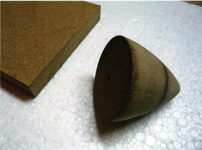
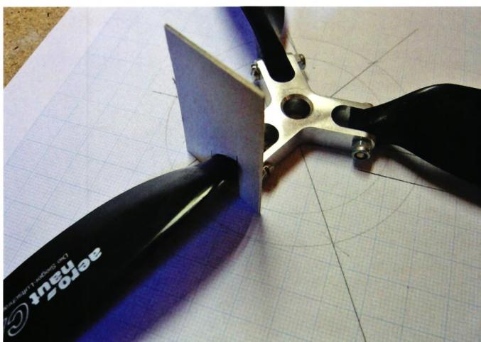
The pictures above, 3a ... 3d, show the process of machining the spinner cap, starting with a mark at a height of about 4 mm (using a waterproof marker, resting on the table—while slowly rotating the spinner cap). This work must be done precisely; otherwise, the spinner will “wobble” later!
A floor plan helps in marking the cutout positions on the drilled cap. Using the cardboard cutout template (Figure 4), it’s quite easy to create three propeller cutouts of equal size.
The Forex base plate is machined on the lathe. It is important to leave a 2-mm stop groove around the outer circumference so that the cap is precisely centered when it is later screwed into place.
The material thickness around the perimeter of the cap decreased from 2 mm to 1.5 mm—a reduction of 25%—during the deep-drawing process; this is a measurement we would have liked to have known when manufacturing the master mold...
After a fruitless search for an M2.5 pan-head screw long enough, I made the center screw out of two M2.5 countersunk screws and
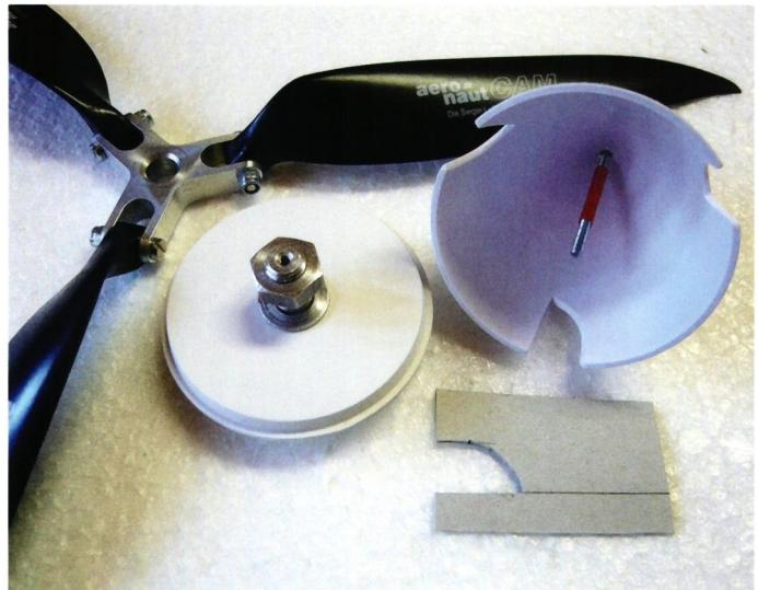
I made it myself from a piece of Bowden cable outer tube. The genius part: It’s permanently attached to the spinner cap!
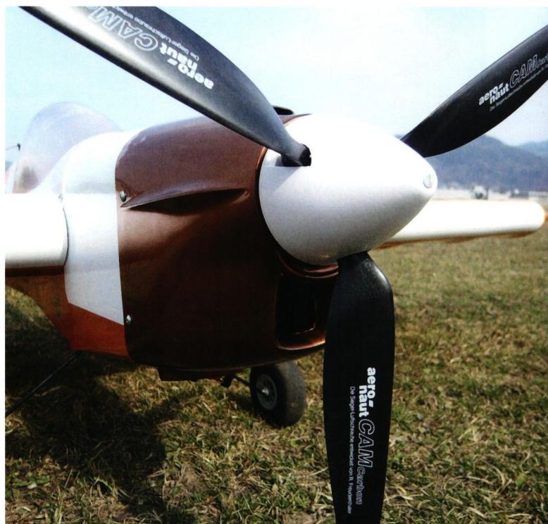
Figure 6 shows the homemade spinner in action. The concentricity was perfect right from the start, and the vibration-free operation at 370 W and 6,900 rpm confirms to me that
the design—at least in this size—is sufficiently stable.
Of course, a spinner like this doesn’t cause much of a stir at the airfield, but it’s still a great feeling when a part you designed yourself comes out on top during flight!
Ruedi Schmid, MG Thun


News from HEBU

PRIDE AND GOOD IDEAS
 Markus Nussbaumer

TEAM MANAGER "THIS" BOSSHARD
 Rodito Nussbaumer

YOU KNOW WHAT I MEAN? 125 YEARS OF THE SWISS AERO CLUB
 Emil Giezendanner

F3A EUROPEAN CHAMPIONSHIPS IN ST-MACAIRE, FRANCE
 Matthias Bosshard

HORIZON HOBBY/LEMACO NEWS: MICRO OV-10 BRONCO 645 MM BY E-FLITE

ATOM, THE NEW DOUBLE-DECKER FROM CPLR
Matthias Bosshard
SUMMER FUN 2026 AT MG USTER
Martin Wunderli
52. 2026 ALPS CUP
Emil Giezendanner
TWIN TOWN PARTNERSHIP
Wolfgang Voeller
CORSAIR F4U – A WARBIRD WITH A MEMORABLE LOOK
Jürgen Rosenberger, Jürgen Prinz
SMALL, MODEL-LIKE SAILBOATS
Res Dauwalder
TRY-OUT DAY AT MFV WETTINGEN
Urs Keller
WELCOME, NEW MEMBER!
Andrea Bolliger
What's New at Leomotion.com

COUPE DES ALPES – OBSERVE AND LEARN
Rodito Nussbaumer
EURO CONTEST GLIDER ACRO TOUR AUSTRIA 2026

BY YOUTH, FOR YOUTH
Lorena Betschen
INSIGHTS INTO THE HISTORY OF SEAPLANES

34th HAHNENMOOS ALPINE MODEL AIRPLANE CAMP
Res Dauwalder
FREE FLIGHT IN THE MIDDLE OF SUMMER
Urs Muntwyler
THE PC-21 STORY
Emil Giezendanner
NEWS FROM HEBU
 Julia Bucher

FROM 0 TO 100
Markus Nussbaumer
MEMORIES
Wolfgang Völler
NOS REGION – A HUB FOR ELECTRIC AVIATION
Emil Giezendanner
DO YOU KNOW WHAT I MEAN IN THE LAND OF SMILES?
Emil Giezendanner
Have you almost forgotten about aircraft that take off and land vertically?
Emil Giezendanner