
A Short Journey Through Time
Building a replica of a world-record-breaking model—now that would be an interesting project!
A glider model that set a world endurance flight record—and without remote control, since this was back in 1944.
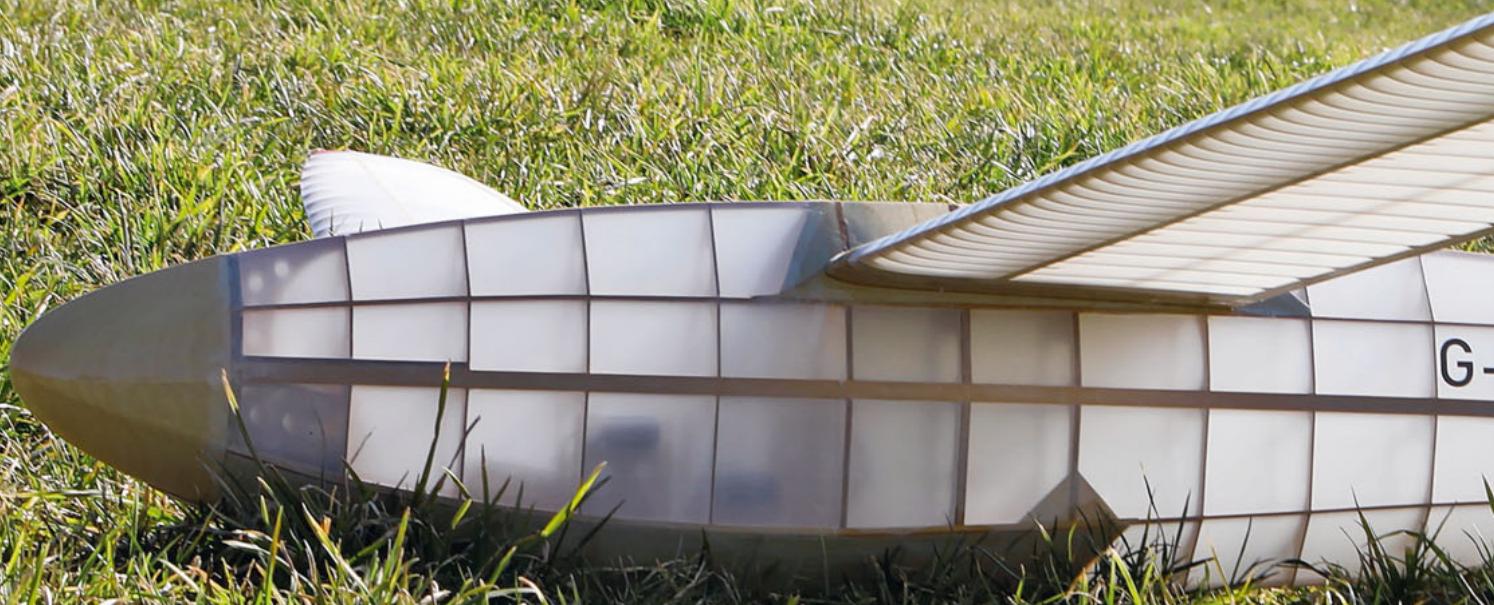
I’ve been interested in building this model and planning to do so for several years now.
I’ve also had the construction plans for quite some time. Countless times I’ve studied the plans and then set them aside again. Many questions about the construction process kept coming to mind. There aren’t even any building instructions—just the construction plans, which are self-explanatory.
Countless parts must be precisely cut from aircraft plywood. Covering the model’s delicate frame with silk and applying a tension varnish without warping the parts is another challenge. I’ve never built such a complex antique model before. But the prospect of flying the model, equipped with a remote control, definitely piqued my curiosity. Rediscovering old construction techniques also has its charm! From a construction standpoint, this is a journey back in time to 1941, the year the G-41 was designed.
The record-breaking flight was set by Traugott Haslach during the regional qualifying competition for Region 5 Zurich
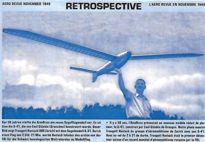
achieved on June 4, 1944, in Bülach. The August 1944 issue of *Aero Revue* featured a detailed report on the world record flight.
Emil Glünkin (1908–2004) of Switzerland was a very well-known model aircraft designer in the 1940s, the heyday of Swiss model aviation. Among other things, he designed the Aroser 36 glider model. This model was designated G-36. Thus, the “G” likely stands for Glünkin, and the “36” or “41” for the year of construction.
His model designs were ingenious and highly successful. Emil Glünkin’s model-flying skills and qualities were truly impressive. The Swiss Aero Club also appointed him as a blueprint reviewer. This role served, so to speak, as quality assurance for model aircraft blueprints. Later, Emil Glünkin was named an honorary member of Region 5.
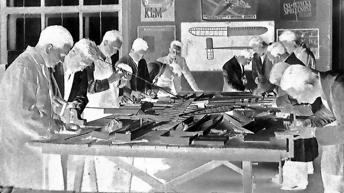
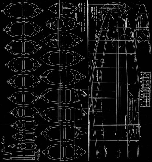
All frames and ribs are drawn very neatly. The fuselage and wings are shown separately on a single sheet. Only the front and rear sections of the fuselage are drawn. Similarly, only the root section and the wingtip of the wing are shown. For that time, this diagram was entirely sufficient. People simply knew how to build such models. The necessary knowledge for building model airplanes was taught back then in construction courses offered by model flying clubs and in schools.
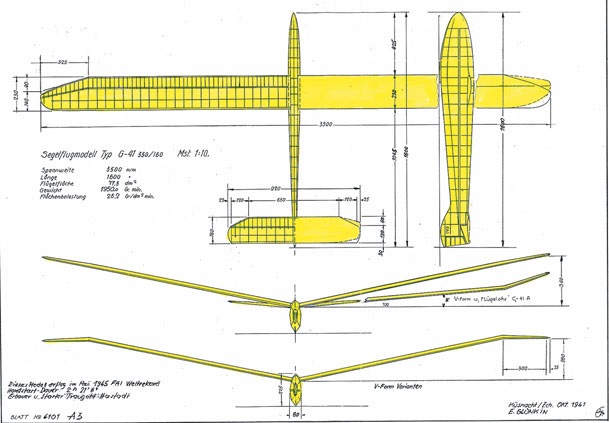
The three-view drawing shows three variations for the V-shape and two variations for the basic shape of the elevators and the wing tips. For aesthetic reasons, I opted for the double V-shape and the forward-rounded trailing edges on the wings and the elevator. On the construction plan, this is variant G-41A.
The model was originally designed as a free-flight model, in keeping with the times. Remote controls, as we use them in our models today, were simply unimaginable back then! To install a remote control now, before construction begins—
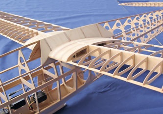
I’m still making various design adjustments. I need to figure out how to install the two servos, the receiver, and the battery—and ensure they’re accessible. Once the fuselage is covered, access will be somewhat limited. To test the linkage and the deflection mechanism for the ailerons and elevator, I first built a simple functional model. The rudder and elevator are linked on both sides using Radioskala cord. The plug-in tab for wing attachment—which was common for free-flight models at the time—is replaced by a flat steel bar standing on its edge.
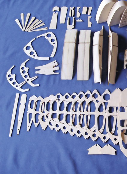
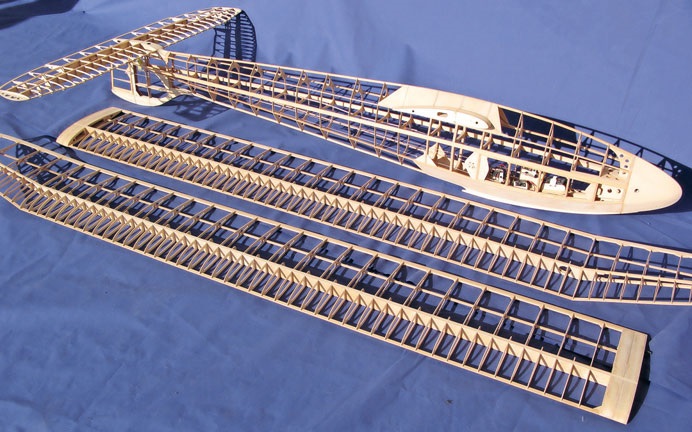
Making the fuselage frames and ribs is purely painstaking work. With et-
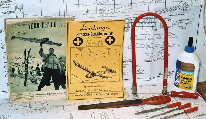
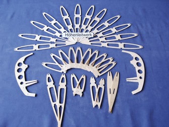
With a little practice, thin aircraft plywood can be worked very nicely and efficiently. Working with great precision really pays off, at the latest, when assembling the fuselage on the slipway. As a former trained toolmaker, I was able to prove myself once again when it comes to precision work! Using a scroll saw, a disc sander, and a Dremel handheld sander converted into a table router, all components can be produced with ease. The wing ribs are manufactured using the block method. The cutouts in the ribs and frames are pre-cut and finished on the table router using a small, very sharp carbide router bit. All slots in the frames and ribs are finished with needle files to achieve the necessary fit for the pine strips. You don’t necessarily need an expensive CNC router to make all the parts. Time-tested craftsmanship and a healthy dose of perseverance work just as well!
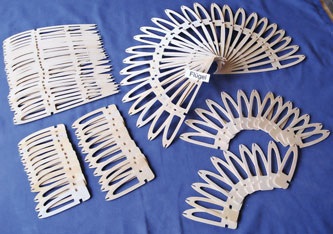
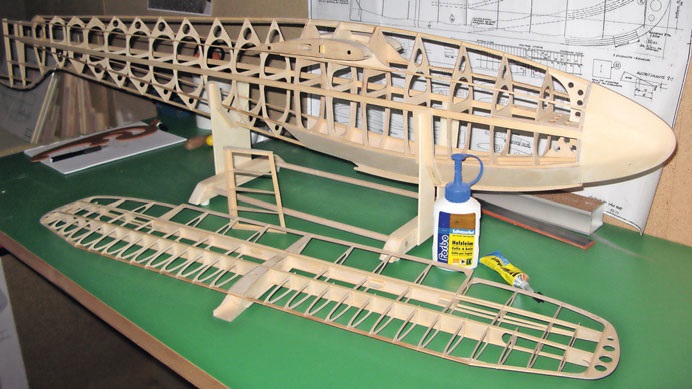
...maintain the same spacing. The entire construction of the wing and the elevator is done using traditional model-building techniques. The plan is placed on the workboard and protected with plastic sheeting. Next, the ribs are attached to the lower spar. After inserting the upper spar, the spar box is installed continuously between the ribs. White glue is used to join the ribs and pine strips to the spar boxes.
Describing the complete construction of the model in all its details and challenges would go beyond the scope of this report. The sequence for building the fuselage and wings must be worked out and determined by the builder himself.
But that is precisely what makes our hobby so interesting—figuring out the solution on your own and enjoying the result in the end. The construction of the fuselage is complete once the receiver’s two servos and the battery have been installed. It is important here to ensure that everything is installed and ready to function. A access panel is attached to the side of the fuselage to ensure easy access to the receiver system.
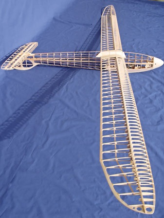
After a lengthy construction phase, the model's structural framework was fully completed.
The fuselage is built on a slipway. Precise alignment of the fuselage strips is crucial here. As the pine strips are inserted and glued, the fuselage quickly takes shape. To shape the rudder, the pine strips must be soaked, glued, and then clamped into molding jigs. Once dry, the strips retain their desired shape and can be installed without tension. The fuselage nose is shaped from linden wood and features an internal cavity to accommodate trim lead.
I quickly redrew the plans for the left and right wings, as well as for the elevator, in CAD. The original plan shows only the wing root and the wing tip. Between the wing root and the wing tip, the ribs in-
but it would have been a complete stylistic mismatch. So I decided on a classic silk covering, even though I knew this would involve a great deal of additional work. After purchasing the Pongé-05 silk—also known as parachute silk—I was able to begin stretching the canvas. By the way, the silk is available at Boesner art supplies in rolls measuring 10 m by 1.4 m.
When it comes to covering model airplanes with silk, you’ll find a variety of tips and methods in the technical literature and on the Internet. The same applies to the mixing ratio of the adhesive—
varnish and thinner. In most cases, the silk is applied wet to the frame, stretched slightly, and secured to the end strips and nose strips with undiluted stretching varnish.
After the silk has dried, it is treated with stretching varnish several times.
To determine my own strategy for covering the wing with silk, I quickly built a test wing out of spare ribs to use as a practice model. I used this practice model to practice applying the silk, securing it, and then coating it with tension varnish. After various trials, my strategy is as follows: The weave direction of the silk should run perpendicular to the ribs, which results in better tension of the silk.
The cut silk is placed dry on the underside of the wing. The silk is first secured to the wingtip spar using undiluted tension varnish. Next, the silk is gently tensioned and secured to the lower spar and the leading edge with tension varnish. The silk is pulled over to the top of the wing and secured to the upper spar and the wingtip spar with tension varnish. The only overlap of the silk is thus on the underside of the wingtip spar and is therefore barely visible. In the next step
The silk is moistened with hot steam from the iron. Immediately afterward, the silk is dried with warm air from a hair dryer. This causes the silk to stretch very easily. The mixing ratio for the stretching varnish is $2/3 stretching varnish and $1/3 thinner.
Apply the tension varnish with a very soft brush. It is very important to brush in the longitudinal direction toward the ribs; otherwise, the varnish will be wiped off by the ribs. The tension varnish must be applied very carefully to prevent it from seeping through the silk. After each coat, the wing must be secured to the workboard. Between coats of tension varnish, the wing should be left to dry on the workboard for 2 to 3 days. This prevents the wing from warping.
After 6 to 7 coats of stretching varnish, the silk is nicely stretched. The entire silk covering gives the model additional dimensional stability and strength.
The smell of the covering varnish also brings back memories of my youth. As I was covering the little Graupner Uhu—completely carefree—the smell of the varnish filled the entire apartment. To protect myself from the smell—or rather, the fumes—of the tension varnish when working with it today, I always wear a half-mask respirator with an A2 gas filter. It’s also important to ventilate the workspace well!
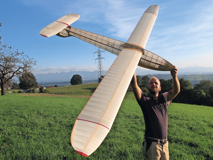
In keeping with the spirit of the times, I labeled the model very simply.
I designed the lettering and the obligatory Swiss crosses on the computer and then made them myself using water-slide decals. Finally, I applied a thin protective coat of clear satin-finish acrylic varnish to the entire model. Installing the remote control, checking the EWD, and determining the center of gravity are all done quickly. The construction plan does not include any information on the center of gravity. The exact center of gravity must be determined through test flights anyway. After a lengthy construction period, my son Christian was able to photograph the fully assembled model.
I invested quite a bit of time in manual labor and brainstorming to build this model.
But I really enjoyed working with aircraft plywood, pine strips, and white glue. Building a historical model is, after all, also a journey through time. Researching the model’s history in old magazines, books, and online is always very exciting. It’s amazing what you can discover there! That’s certainly another interesting aspect of our hobby!
If you’re allergic to fiberglass or balsa sanding dust, it’s best to build models out of aircraft plywood and pine! It’s much more pleasant and healthier!
For potential building projects, you’ll find some very exciting models in the plan archive of the Albatros Oldtimer Glider Aircraft Association.
Now I’m looking forward to the maiden flight and the upcoming flights in the thermals! Of course, this is a model meant to be enjoyed and flown—after all, the G-41 is actually a free-flight model! I’ll be happy to report on my flying experiences and whether I manage to break the former world endurance flight record in a future issue of “Modellflugsport.”


News from HEBU

TEAM MANAGER "THIS" BOSSHARD
 Rodito Nussbaumer

YOU KNOW WHAT I MEAN? 125 YEARS OF THE SWISS AERO CLUB
 Emil Giezendanner

F3A EUROPEAN CHAMPIONSHIPS IN ST-MACAIRE, FRANCE
 Matthias Bosshard

52. 2026 ALPS CUP
Emil Giezendanner
PRIDE AND GOOD IDEAS
 Markus Nussbaumer

ATOM, THE NEW DOUBLE-DECKER FROM CPLR
Matthias Bosshard
CORSAIR F4U – A WARBIRD WITH A MEMORABLE LOOK
Jürgen Rosenberger, Jürgen Prinz
SUMMER FUN 2026 AT MG USTER
Martin Wunderli
TRY-OUT DAY AT MFV WETTINGEN
Urs Keller
TWIN TOWN PARTNERSHIP
Wolfgang Voeller
BY YOUTH, FOR YOUTH
Lorena Betschen
SMALL, MODEL-LIKE SAILBOATS
Res Dauwalder
What's New at Leomotion.com

HORIZON HOBBY/LEMACO NEWS: MICRO OV-10 BRONCO 645 MM BY E-FLITE

COUPE DES ALPES – OBSERVE AND LEARN
Rodito Nussbaumer
EURO CONTEST GLIDER ACRO TOUR AUSTRIA 2026

INSIGHTS INTO THE HISTORY OF SEAPLANES

34th HAHNENMOOS ALPINE MODEL AIRPLANE CAMP
Res Dauwalder
WELCOME, NEW MEMBER!
Andrea Bolliger
FREE FLIGHT IN THE MIDDLE OF SUMMER
Urs Muntwyler
THE PC-21 STORY
Emil Giezendanner
NEWS FROM HEBU
 Julia Bucher

FROM 0 TO 100
Markus Nussbaumer
MEMORIES
Wolfgang Völler
NOS REGION – A HUB FOR ELECTRIC AVIATION
Emil Giezendanner
Have you almost forgotten about aircraft that take off and land vertically?
Emil Giezendanner
DO YOU KNOW WHAT I MEAN IN THE LAND OF SMILES?
Emil Giezendanner