
A Speedy 30s-Era Plane – RYAN STA with a 2,350 mm Wingspan
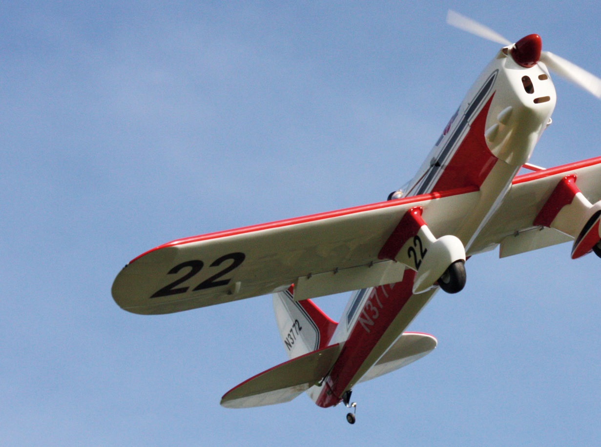
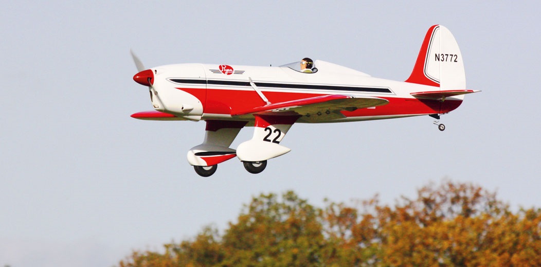
The Ryan STA is a product of the “Golden Age.” It was developed in 1933 by T. Claude Ryan, the designer and entrepreneur who had previously designed the legendary “Spirit of St. Louis,” in which Charles Lindbergh made the first solo transatlantic flight in 1927. The Ryan STA has a distinctive shape, which is why model airplane enthusiasts have always enjoyed building replicas of it. It’s never been easier than it is today, because Pichler Modellbau offers the model as an ARF (Almost Ready to Fly) kit with a choice of 1,800 or 2,350 mm wingspan, prefabricated by Black Horse in Vietnam. This report focuses on the larger version, because “big is beautiful.”
The 1930s are rightly considered the golden age of aviation. For the first time, aircraft designers felt that “anything goes,” which inspired them to roll up their sleeves and try entirely new things. Lightweight yet sufficiently reliable engines were finally available. Wings could be built large enough and stable enough to avoid needing multiple ones. And people were already beginning to unravel the laws of aerodynamics. We likely have these efforts to thank for the characteristic wheel fairings, even if today—now that such things can be measured in a wind tunnel—we arrive at different conclusions.
The original designation of this sleek and elegant-looking low-wing aircraft was Ryan ST. The abbreviation stood for “Sport Trainer.” The open two-seater was initially powered by a 95 PS Menasco B4 engine. Later, power was increased to 125 PS, resulting in the Ryan ST-A (Aerobatic). A high-performance sports version eventually received a turbocharged 150 PS engine and an auxiliary fuel tank in place of the front pilot’s seat. And that brings us to the basis for the Black Horse test model, which can be powered either by an electric motor or an internal combustion engine.
If you have to assemble it on the kitchen table of a two-room granny flat, a 2,350-mm span might not be the right choice. Because even though the prefabrication is extremely advanced and the rectangular surface with its rounded edge arches can naturally be divided, you simply need plenty of space on all sides to finally be able to put the thing together. And with a fuselage length of 172 cm and an elevator span of nearly 80 cm (fixed), the model is designed to be climate-neutral in a timely manner.
Bicycle trailers are, after all, no longer the mode of transportation of choice. But once the layout issues are settled, there’s nothing—absolutely nothing—standing in the way of the XXL version, which—to anticipate the outcome—will also be confirmed in later flight tests. Word has probably already gotten around that even ARF models still need to be assembled before they’re ready to fly. As for the time required for this, it matters less how many control hinges need to be glued in place and how many Bowden cables need to be cut to length, and more whether the overall design is truly well thought out and nothing that appears to be “ready-made” needs to be reworked. And here, the model specialists in Saigon deserve high marks in nearly every respect. If the screws, neatly packed in plastic bags, hadn’t been counted just a bit too sparingly, and if the number of included control hinges had actually been sufficient, there would be almost nothing to complain about. But when you look at it objectively, these are minor issues, because anyone who builds a model like this already has those kinds of parts on hand.
If you follow the English, richly illustrated assembly instructions, construction begins with completing the wings. You’ll need to install hinges, as well as servos and linkages for the ailerons and landing flaps. The installation is perfectly prepared, and the 3-mm control linkages are already cut to length. In keeping with the model’s scale, 4-mm pin hinges and two-pronged control horns are used, with their mounting holes precisely pre-drilled. Regarding the flaps, which are hinged out of sight, there is a subtle point to note: the servos can be installed in two ways: first, as is generally customary, symmetrically on both sides so that both servos operate in opposite directions; or, with both servos’ output on the same side so that they can later operate in the same direction. This allows both flaps to be controlled via a V-cable using a single receiver output. It’s also worth noting that, for a model of this size, the control forces—which are not insignificant when the flaps are fully extended—must pass through the pivot point of the servo shaft to spare the control mechanisms from prolonged holding or current loads. The instruction manual recommends a downward deflection of 25 mm for the flaps. You might as well factor in a little extra clearance right now.
The installation of the main landing gear that follows now warrants a few brief comments. At its core are sturdy metal, linearly spring-loaded telescopic legs, which are mounted via
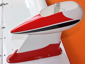
Mounting crosses are attached to the wings. There are no complaints about the performance of this suspension system. However, as every experienced model pilot knows, the landing gear legs—which are 24 centimeters long from the mounting point to the wheel axle—are subjected to stress not only vertically but also horizontally during landing; a problem that is commonly addressed today with a trailing suspension system. And indeed: Even after the first few—quite “decent”—landings, increasing play became apparent at the pinned connection between the mounting cross and the suspension strut, causing the tire treads to start wearing down at the rear cutout of the wheel shoes. I solved the problem to my own satisfaction by filling the resulting gap with UHU endfest 300 heated to 15 to 180 degrees (due to its viscosity and subsequent strength!) UHU endfest 300 and reinforcing the heavily loaded joint with a sort of collar made of carbon fiber roving using the bonding technique mentioned above. Another solution would likely be to mount the upper part of the wheel fairing on spring-loaded mounts as well, which would be technically feasible.
There isn’t much to say about the fuselage construction. A removable fuselage back panel, which fits almost like a suction cup when attached, facilitates access to the internal components. Standard-size servos measuring 21 × 42 mm (width × length) are suitable. As is now standard for models in this size class, each elevator link is operated by its own servo. The control linkage is designed to use 2.5 mm-thick steel pushrods guided through pre-installed plastic tubes. They seemed a bit too heavy to me, so I replaced them with carbon rods. Otherwise, everything appears to be quite sturdily built. The control horns for the elevator and rudder are milled from fiberglass-reinforced plastic (FRP) and are connected to the pushrods via ball joints using 3-mm screws. The included spring-loaded tailwheel with wire-frame suspension won’t exactly thrill scale enthusiasts, but it scores points for functionality.
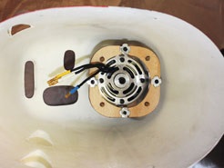
As previously described, the Pichler Ryan can be powered by either an electric motor or an internal combustion engine. If you opt for the latter, the installation is well-prepared and described in great detail. For electric drive, as chosen here, installation materials such as a mounting board, spacer sleeves, and long screws are also included. However, they seem to be intended more for a “small motor.” To accommodate the sporty, acrobatic
| Wingspan: | 2,350 mm |
| Fuselage length: | 1,720 mm |
| Weight: | 6,985 g |
| Wing area: | 80.7 dm² |
| Wing loading: | approx. 87 g/dm² |
| Spinner diameter: | 80 mm |
| Battery: | LiPo 10s 4500 mAh RED POWER 25C |
| Motor: | Pichler BOOST 140 (235 kV) |
| Speed controller: | SPIN PRO 99 opto |
| Propeller: | 19 × 8 to 20 × 10 inches |
| 5 V power supply: | HV-BEC from KETO, 6 and 50 V (2 to 12s LiPo), 10/20 A |
In my case, the new engine mount consists solely of four fiberglass-reinforced plastic (FRP) tubes with an outer diameter of 6 mm and a wall thickness of 1 mm, which were first smoothed with a slight allowance and then sanded down to a smooth finish at the ends. To better absorb torsional forces, the tubes do not run parallel but converge slightly diagonally toward the front. They are inserted on both sides into correspondingly angled holes with the smallest possible clearance (6.5 to 7 mm) and are generously coated at the joints with slow-curing (!) epoxy adhesive; they are then best temporarily secured with rubber rings or masking tape. After reassembling the fuselage and canopy and checking once more to ensure everything fits correctly (easily done from the rear through the cut-out fire bulkhead), allow the entire assembly to cure overnight. Afterward, if necessary, the bonded joints can be reinforced from the outside with thickened resin, as shown in the picture. Provided the described steps are carried out properly, this type of engine mount is unbeatable in terms of strength-to-weight ratio. If everything was done correctly, the spinner will then rotate exactly parallel to the front panel. To complete the powerplant installation, a 100-A opto-speed controller finds a sufficiently cool spot beneath the motor dome.
A 10s Red Power LiPo with 4500 mAh was installed on the battery tray to provide power. As would later become apparent when weighing the model, it is easily accessible in the front section via the upper fuselage opening and is therefore also easy to replace.
As for the receiver’s power supply, I’ve always preferred to rely on the good old nickel-cadmium battery, which, with minimal maintenance, outshone everything else in terms of ruggedness and reliability. Unfortunately, these cells are no longer available in the originally guaranteed (Sanyo) quality. For power systems up to 6s, the BEC system integrated into the speed controller has long since become the standard; when used properly and under moderate load, it can be considered safe. Although there are also controllers on the market that include a reliable BEC for voltages above 6s, they unfortunately come at a disproportionately high price that isn’t necessarily justified by the additional cost. A cost-effective alternative is the HV-BEC from KETO (distributed by Höllein), which can handle input voltages between 6 and 50 V (2 to 12s LiPo), handles a current load of 10/20 A, and offers selectable output voltages ranging from 5 to 8.4 V (the latter, of course, only at a correspondingly high input voltage). As a short-term buffer (to reassure the pilot), two capacitors with a total capacity of 660 µF/10 V ensure stability on the power supply lines.
After applying the extensive decals—for which it’s best to use a little dishwater to help slide the decal sheets back and forth a bit at first—it’s time to adjust and balance the model. The model, weighing just under 7 kilograms, has a target center of gravity 100 mm behind the leading edge.
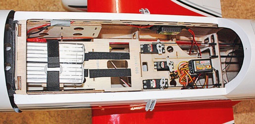
There seems to be a reassuring degree of safety built in. However, this value can be adjusted to be completely lead-free by sliding the flight battery almost all the way forward. The control surface travel also looks as if the designers really didn’t want to take any risks. It’s recommended to use dual rate to set up a sort of “gentle mode,” in which, for example, the elevator has very little travel at the end stops (±10 mm). Those with a bit of experience in large-scale modeling can safely go with the higher settings right from the start. A 20x13 Graupner E-Prop had the honor of leading the way on the first flight.
Well, honorable tasks are rarely without risk. More than expected, the lever effect kicked in during the initial acceleration on the runway and pulled the nose of the plane toward the ground. With the elevator travel set very low as recommended, you have almost no chance of making a corrective maneuver at the last second. In short, the first takeoff attempt ended fatally—for the propeller, at any rate.
Well, as long as that’s all it is! On the next attempt, we celebrated with an elevator deflection nearly doubled and a more delicate acceleration, keeping the elevator at full travel at first and then reducing it as speed increased. This time, the aircraft takes off after a 25-meter roll and transitions into a brisk climb. No further trim adjustments are really necessary; the flight is smooth and stable. The responses to the controls are somewhat subdued, suggesting that the center of gravity could still be moved back a few millimeters. There is also still some room for improvement regarding control surface travel. The first landing—well before the battery runs out—is performed without using the flaps and, with a slight overshoot, is smooth and trouble-free. Nevertheless, the left wheel fairing at the rear edge of the wheel well shows slight signs of contact with the ground. The 24-cm-long telescopic shock absorber simply cannot help but “bounce” backward as well. It

When adjusting the landing gear fairing, it is therefore recommended to leave some space at the rear of the wheel well. The subsequent test flights with the battery shifted 20 mm backward and the corresponding center of gravity shift showed significantly more dynamic, yet still stable, flight behavior. The specified flap deflection of 25 mm downward can safely be increased to 40 mm. This results in a noticeably reduced landing speed even without elevator input. For the other control surfaces as well, the control travel can be increased by 60 to 80 percent without the model feeling twitchy in any way.
From this point on, you can simply enjoy the Ryan’s flight characteristics. Its size ensures smooth handling even in slightly windy conditions. The 20-inch propeller has enough thrust to allow for near-vertical flight at times. Thanks to the powerful propulsion, the “A” in the model’s name certainly lives up to its reputation. The model’s build quality conveys a sense of quality and stability even during flight. Pilots who have mastered it can perform any type of classic aerobatics with the RYAN STA. Flying upside down close to the ground takes some getting used to, because the model then looks as if it’s stretching its sturdy legs helplessly toward the sky. Yes, maybe it’s time to try something truly unusual. The endless repetition of the same old flight patterns is a thing of the past.
An exceptionally beautiful, well-built model with pleasant, trouble-free flight characteristics at an acceptable price. Visually, it clearly stands out from the crowd of models commonly found at our airfields. You shouldn’t skimp on the motorization, because the RYAN STA has sportiness in its DNA. Of course, the same rule applies here: Flying means landing! As for the landing gear design, the folks in faraway Saigon to the east might want to come up with something new. On the other hand: Aren’t we model airplane enthusiasts famous for our creativity? The acronym ARF shouldn’t stop us from continuing to cultivate our core competence in the future! ■
*Photos: Axel Brand and Ludwig Retzbach*


News from HEBU

TEAM MANAGER "THIS" BOSSHARD
 Rodito Nussbaumer

YOU KNOW WHAT I MEAN? 125 YEARS OF THE SWISS AERO CLUB
 Emil Giezendanner

HORIZON HOBBY/LEMACO NEWS: MICRO OV-10 BRONCO 645 MM BY E-FLITE

PRIDE AND GOOD IDEAS
 Markus Nussbaumer

TRY-OUT DAY AT MFV WETTINGEN
Urs Keller
F3A EUROPEAN CHAMPIONSHIPS IN ST-MACAIRE, FRANCE
 Matthias Bosshard

52. 2026 ALPS CUP
Emil Giezendanner
ATOM, THE NEW DOUBLE-DECKER FROM CPLR
Matthias Bosshard
SUMMER FUN 2026 AT MG USTER
Martin Wunderli
What's New at Leomotion.com

COUPE DES ALPES – OBSERVE AND LEARN
Rodito Nussbaumer
TWIN TOWN PARTNERSHIP
Wolfgang Voeller
BY YOUTH, FOR YOUTH
Lorena Betschen
34th HAHNENMOOS ALPINE MODEL AIRPLANE CAMP
Res Dauwalder
CORSAIR F4U – A WARBIRD WITH A MEMORABLE LOOK
Jürgen Rosenberger, Jürgen Prinz
SMALL, MODEL-LIKE SAILBOATS
Res Dauwalder
WELCOME, NEW MEMBER!
Andrea Bolliger
FREE FLIGHT IN THE MIDDLE OF SUMMER
Urs Muntwyler
EURO CONTEST GLIDER ACRO TOUR AUSTRIA 2026

INSIGHTS INTO THE HISTORY OF SEAPLANES

THE PC-21 STORY
Emil Giezendanner
NEWS FROM HEBU
 Julia Bucher

FROM 0 TO 100
Markus Nussbaumer
MEMORIES
Wolfgang Völler
NOS REGION – A HUB FOR ELECTRIC AVIATION
Emil Giezendanner
DO YOU KNOW WHAT I MEAN IN THE LAND OF SMILES?
Emil Giezendanner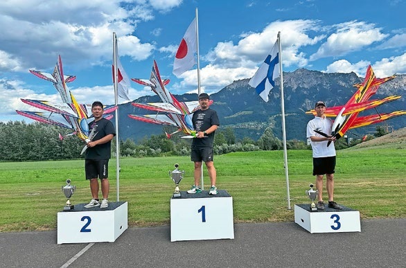
A SPECTACULAR F3A WORLD CUP IN THE PRINCIPALITY OF LIECHTENSTEIN
Emil Giezendanner