
Funblei Instead of Funray
The Funray didn't have enough thrust for me, so I had to do something about it. My first attempt with 342 grams of ballast didn’t quite convince me, so I decided to add 1 kg of ballast. The flight weight with 1 kg of ballast and a 4S battery is 3060 grams.
The ballast can be positioned exactly at the center of gravity if the space beneath the wing is used for this purpose. However, this requires that the center of mass of the ballast be located 80 mm in front of the rear end of the ballast and that the ballast can be pushed all the way to the back so that the center of gravity is correct.
To ensure the ballast fits perfectly, it should be 160 mm long; this way, it won’t protrude at the front, and the battery (400 g) can still be pushed all the way to the back. The width of 58 mm ensures that it cannot move sideways once it is fully inserted. The height of 17 mm to 21 mm ensures that it is also secured in this direction of movement. At a length of 160 mm, the center of mass must be located in the middle of the ballast.
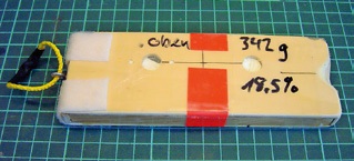
The string at the front end is there to make sure the ballast can be easily pulled out again.
The top side of the ballast is visible! The Velcro fasteners on the bottom (!) adhere to the counterparts glued into the fuselage. I pulled them up to the top side so they wouldn’t come loose. The Velcro on the front and top sides therefore has no adhesive function!
There is an exception visible on the right side at the end of the ballast. Without this exception, the ballast cannot be pushed far enough back, because otherwise the servo cables for HLW and SLW would prevent it from being pushed all the way back.
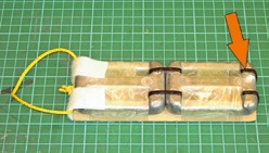
The 1-kg weight is taller: 24 mm with cable ties, 20 mm without. There are also cable ties under the Velcro fasteners. The cable ties secure two 500-g diving weights (ordered from Decathlon, listed as “lead weights”) lengthwise onto a 2-mm-thick sheet of aircraft plywood, which is secured crosswise and vertically with 38-mm Tesa tape. The ballast still fits, but it’s a very tight fit. I also carved out a recess at the rear end; see the orange arrow.
Furthermore, I used a screwdriver to enlarge the hole toward the top through an exhaust vent under the wing, through which the servo cables for the horizontal and vertical stabilizers are routed toward the rear. The ballast can be pushed all the way to the rear. The center of gravity is definitely correct when the 4S battery weighs 400 g and is pushed all the way to the rear, and the steel ball in the tail is also positioned there.
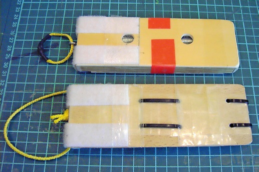
In addition to attaching the Velcro fasteners to the ballast with adhesive, I also secured them at the back end with tape by wrapping the tape around both the ballast and the Velcro. However, the slider (see below) can get stuck in there and then can’t be pushed in far enough. So make sure to wrap the tape only around the last centimeter.
The Velcro fasteners in the fuselage for securing the ballast begin where the CFRP square tube disappears into the foam and extend approximately 3 cm toward the rear.
Before the ballast is put in place, the servo cables for elevator and aileron—channels 2 and 4 on Futaba transmitters—need to be adjusted on the receiver because they are longer than those for the wings. I then wrapped the cables with a piece of double-sided Velcro to keep them reasonably secure. Masking tape would work, of course. I’d also check the other channels—you may need to adjust the servo cables on those as well.
While inserting the ballast, gently pull on the cables straight toward the front so that they are taut and the servo cables for elevator and aileron are in
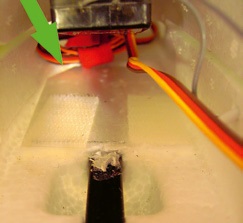
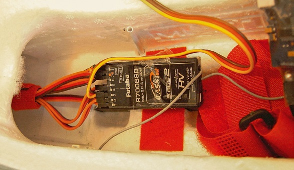
Insert the intricate exception piece. The receiver is inserted later, with the top side facing down, and glued in place at the top. The two Velcro fasteners glued to the fuselage, to which the ballast is attached, are hard to see because they are white.
You need a tool to insert and remove the ballast; I call it a “pusher” because you slide it in so that the ballast doesn’t stick to the Velcro fasteners while you’re inserting it.
You also need this pusher to remove the ballast, to separate it from the Velcro attached to the fuselage. The tricky part is that the pusher can bump against the Velcro attached to the fuselage, and then you can’t get it in :-)
The slider is cut from a Biella pencil case and then wrapped with 38-mm Tesa tape to stiffen it up a bit.
The colored stripes are only there to make it easier to spot inside the airplane’s shipping box.
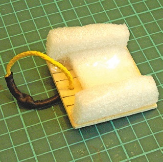
The clamp that presses the ballast downward and thereby secures the Velcro fastener.
The white material is cut-to-size packaging foam. The receiver is then placed between the two walls.
The receiver has Velcro on the underside and is attached to the fuselage with the underside facing up, adhering to the counterpart glued there. Next, the clamping piece is inserted and presses the receiver
upward and the ballast downward.
I would like to point out that the antennas are very vulnerable when they are attached to the fuselage, because manipulating the ballast and the clamping piece can quickly cause the antennas to break.
The aircraft's weight increases by 50% with 1 kg of lead. The new flight weight is 3,060 grams. These 3 kg need to be accelerated, which will likely require more power
. Perhaps it would work with 3S as well, but I wanted to play it safe and switch to 4S. Since the rotational speed is raised to the third power in the propeller’s power consumption, switching from 3S to 4S results in an increase in propeller power of (4/3)³ = 2.35 (factor), which is why a propeller with lower power consumption must be installed. With the right propeller, the current draw remains the same, but due to the higher voltage, the power increases by 33%.
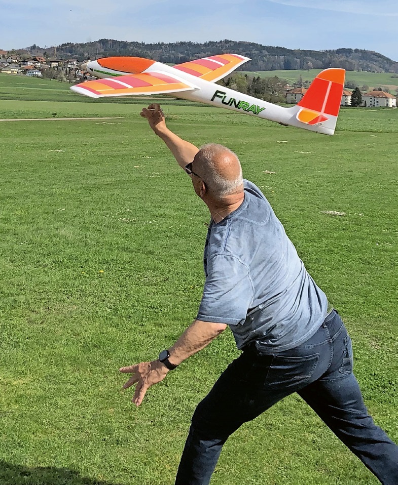
The original folding propeller measures 11 × 7 inches (diameter 27.94 cm) with the matching hub. With the Funray hub, this results in a 12 × 7-inch propeller. I then consulted my propeller conversion chart and, for the switch from 3S to 4S, arrived at the following suitable propellers: either 12 × 7 inches or 11 × 7 inches. Taking
the center hub, we can go, for example, from a 10 × 7 to an 11 × 7, or from a 12 × 7 to a 12 × 5-inch folding propeller.
I then decided on the 11 × 5-inch folding propeller, since climb performance and good acceleration in the lower speed range (hand launch!) are more important to me than flying fast under power.
Just to be on the safe side, Hans-Ruedi helped me launch the plane on the first attempt with 1 kg of lead, a 4S battery, and the 11 × 5-inch propeller—which is actually a 12 × 5-inch propeller because of the center section. Thanks, Hans-Ruedi. The propeller choice turned out to be spot on. That said, it’s worth noting that an 11 × 4-inch folding propeller would also suffice and would even reduce power consumption.
A 50% increase in weight means that the aircraft must fly at a speed that is the square root of 50% faster in order to generate the same lift, because speed is squared in the lift equation. So that means you have to fly 7.1% faster.
While flying at the airfield, it seemed to me that, due to the increased flight weight, the aircraft builds up enough lift to reach that 7.1% without much thought.
When landing, however, you have to be very aware of the 7.1% higher speed required; otherwise, you might crash near the ground. The landing speed increases by 7.1%, unless you extend the flaps a little.
Unfortunately, I haven’t yet been able to test it on a slope, which is actually why I bought the Funray.


TEAM MANAGER "THIS" BOSSHARD
 Rodito Nussbaumer

YOU KNOW WHAT I MEAN? 125 YEARS OF THE SWISS AERO CLUB
 Emil Giezendanner

F3A EUROPEAN CHAMPIONSHIPS IN ST-MACAIRE, FRANCE
 Matthias Bosshard

News from HEBU

SUMMER FUN 2026 AT MG USTER
Martin Wunderli
TRY-OUT DAY AT MFV WETTINGEN
Urs Keller
52. 2026 ALPS CUP
Emil Giezendanner
BY YOUTH, FOR YOUTH
Lorena Betschen
ATOM, THE NEW DOUBLE-DECKER FROM CPLR
Matthias Bosshard
CORSAIR F4U – A WARBIRD WITH A MEMORABLE LOOK
Jürgen Rosenberger, Jürgen Prinz
SMALL, MODEL-LIKE SAILBOATS
Res Dauwalder
What's New at Leomotion.com

TWIN TOWN PARTNERSHIP
Wolfgang Voeller
EURO CONTEST GLIDER ACRO TOUR AUSTRIA 2026

INSIGHTS INTO THE HISTORY OF SEAPLANES

34th HAHNENMOOS ALPINE MODEL AIRPLANE CAMP
Res Dauwalder
HORIZON HOBBY/LEMACO NEWS: MICRO OV-10 BRONCO 645 MM BY E-FLITE

COUPE DES ALPES – OBSERVE AND LEARN
Rodito Nussbaumer
PRIDE AND GOOD IDEAS
 Markus Nussbaumer

FREE FLIGHT IN THE MIDDLE OF SUMMER
Urs Muntwyler
THE PC-21 STORY
Emil Giezendanner
WELCOME, NEW MEMBER!
Andrea Bolliger
NEWS FROM HEBU
 Julia Bucher

FROM 0 TO 100
Markus Nussbaumer
MEMORIES
Wolfgang Völler
NOS REGION – A HUB FOR ELECTRIC AVIATION
Emil Giezendanner
Have you almost forgotten about aircraft that take off and land vertically?
Emil Giezendanner
70 YEARS OF THE NIDWALDEN MODEL AIRPLANE CLUB
Martin Barmettler