
Construction of a Digital Balance Scale
The position of the center of gravity significantly determines the flight characteristics of any aircraft. If it is too far aft, the aircraft is unstable; if it is too far forward, flight performance is inadequate. The position of the center of gravity can be adjusted within a certain range to tailor the flight characteristics to the model’s intended use and the pilot’s skill level.
The optimal position of the center of gravity—specifically for the maiden flight—should always be known: whether through information in the assembly instructions, on the construction plan, or through your own calculations [1] [2] [3].
The position of the center of gravity is still frequently checked using two fingers. A more precise method involves using a commercially available or homemade center-of-gravity scale in the form of a seesaw. Others swear by the Vanessa center-of-gravity scale or attach cleverly placed suspension points to the model. Digital center-of-gravity determination is already possible using just three electronic kitchen scales, which support the model in the correct position and whose positions relative to the reference point for the center of gravity have been measured.
Digital center-of-gravity scales are already commercially available, e.g., [4] with a report in [5]. Some, e.g., [6] and [7], are based on the method described above using three kitchen scales. Three load cells with mounts for the wheels are connected to a microcomputer and aligned and measured on a table according to a specified procedure corresponding to the wheel spacings. The microcomputer calculates
then the total weight and the location of the center of gravity.
More recently, digital center-of-gravity scales have become available that feature a type of weighing pan ([4] and [8]). In the weighing pan, the model lies horizontally with the reference point for center-of-gravity measurement—usually the intersection of the nose strip and the fuselage—resting against a stop. This eliminates the need to measure distances. Designs with one, two, or three load cells (Table 1) have been published [9].
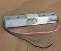
Load cells (Figure 1) are also used in digital kitchen scales. There are various types of load cells; they are usually made from a metal rod with special relief holes in the center and strain gauges attached in appropriate locations. The force of a bending stress applied to this rod causes a change in the resistance of the strain
Load cell. Using a Wheatstone bridge, amplifiers, and an analog-to-digital (A/D) converter, the force can be processed by a microcontroller and ultimately displayed.
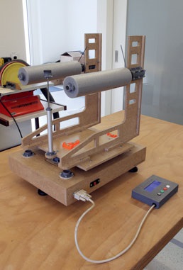
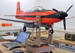
I built a digital center-of-gravity scale (Figure 2) for my typical models (motor-powered models, high-, low-, and mid-wing aircraft, up to about 3 kg total weight) because, as a “mechanic,” I was drawn to the challenge and saw room for improvement in how I determine the center of gravity. This report is not a step-by-step guide with detailed documentation, but is intended to help readers better understand the topic of “digital center-of-gravity scales.” It is meant to
motivate readers to design and build their own suitable center of gravity scale.
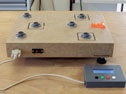
My load cell balance consists of a base frame (Figure 3) with three load cells (2×2 kg and 1×3 kg) and a weighing pan. The base frame rests on three adjustable,
| Number of load cells | Total weight | Center of gravity (longitudinal) | Transverse center of gravity | Remarks |
|---|---|---|---|---|
| 1 | No | Yes | No | Total weight must be measured separately |
| 2 | Yes | Yes | No | By design, torques also act on the sensors |
| 3 | Yes | Yes | Yes | Only forces act on the sensors |
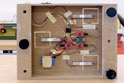
Mounted on sturdy feet. On the top surface, three receptacles for the weighing pan are mounted in recesses, spaced 200 mm apart in both the longitudinal and transverse directions. The feet of the weighing pan, guided into the mounts, transmit the forces to be measured to the base frame via load cells. Inside the base frame (Figure 4) are the necessary electronic components (microcontroller, measurement amplifier with A/D converter), a 2S Li-ion cell for power supply, and the connections to the outside world (connector to the control panel, on/off switch). On the top are three additional, slightly raised mounts for the weighing pan. The weighing pan rests in these when the scale is not in use, so that the load cells are not unintentionally loaded. The base frame also rests on these raised supports when it is placed on top of the scale for maintenance purposes. The weighing pan consists of a base with three height-adjustable spherical feet, two uprights with tubular mounts, and various supports of different lengths. The uprights can be mounted in six different positions: three different positions in the transverse—
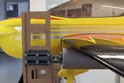
to accommodate different fuselage widths, landing gear configurations, and wing spans, and to extend the scale’s longitudinal measuring range by two positions. The reference point for the measurement can thus be shifted by 50 mm.
The model is placed on the foam-padded tube holders and aligned using two rotatable and longitudinally adjustable stops (Figure 5) made of 2-mm CFRP rods. This also allows for the measurement of models with swept wings. The tubular supports can be attached to the stand at three different heights. The horizontal position of the models is adjusted using a support. I have supports of various lengths (Figure 6)
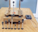
Construct them and equip them with flat, padded heads (for box-shaped fuselages) and V-shaped notched heads (for rounded fuselage undersides). In general, a model can be measured in a normal flight attitude or in a inverted flight attitude. For straight or concave airfoils, the leading edge must either be shimmed in the normal flight position or the measurement must be taken in the inverted flight position.
A microcontroller is the brain of the entire electronic system. I chose a microcontroller from Arduino [10] because these devices are very well documented online
and are easy to program. There are many tutorials (videos) and books available, so the knowledge needed to build a digital center-of-gravity scale can be acquired in a reasonable amount of time. I used an original Arduino Nano to avoid any hassles and to make a small contribution to this fascinating open-source project. Load cells can be recycled from digital kitchen scales. I was only able to find affordable load cells with sufficient accuracy in China [11]. Load cells with identical nominal capacities and connection specifications are available for 1, 2, 3, 5, 10, and 20 kg. These are usually supplied with an amplifier/A/D converter based on the HX711 chip. According to reports on the Internet, not all of them provide good signal quality.
I purchased the amplifier and A/D converter in the U.S. The website [12] provides good documentation and a link to a library [13] required for easily evaluating the measurement results in conjunction with an Arduino Micro controller.
Similarly, when procuring the LCD display [14] [15], I prioritized good documentation over a low price. I chose a four-line display so that I could clearly present the results of the center of gravity measurement.
It would be an exaggeration to claim that I programmed the software myself. There are plenty of resources online addressing the specific problems to be solved. When programming, it’s convenient to proceed in stages. First, I familiarized myself with the LCD. In a subsequent test program, I read out the load cells. The circuitry for the buttons and the measurement of the battery voltage—topics such as—
The introduction to Arduino—I was already familiar with it.
The location of the center of gravity is calculated using the equilibrium of forces and moments. It sounds more complicated than it is; see, for example, [16].
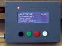
The program is menu-driven (Figure 7, Figure 8). Four buttons (Up, Down, Enter, Menu) allow for easy navigation and selection within the menus.
The main menu consists of four items:
- Center of Gravity: Measuring the center of gravity. First, the scale is zeroed, and then the user is prompted to place the model on it.
- Front/Rear: You must specify whether the stands are mounted in the front or rear position.
- Calibration: Each load cell is calibrated using a known weight. The calibration remains available even after the device is turned off and back on.
- Reset Values: Resets the calibration factors to their original values.
I CNC-milled the main frame and the weighing pan primarily
CNC-milled from 8 mm and 10 mm thick MDF panels. Brackets, fittings, and panel housings are 3D-printed. Many parts, such as aluminum tubes, heating insulation, feet for the base frame, D20 ball knobs (feet for the weighing pan), threaded rods, threaded inserts, screws, nuts, and washers were purchased from a hardware store.
I soldered the electronics onto a breadboard for the base frame (Arduino Nano, three analog-to-digital converters, connectors for the external power supply, on/off switch, and the connection cable to the panel) and onto a breadboard for the panel (push buttons, connectors for the LCD display, the LED, and the connection cable to the base frame).
Before the scale can be tested or used, it must be calibrated with a weight that is, if possible, calibrated or otherwise reliable. Determining the reference weight led to the first insight: My three digital kitchen scales in the workshop displayed results that varied by within 3 g. I decided that one of the three scales displayed the correct result and used that value. The absolute weight is important for measuring the total weight; for measuring the location of the center of gravity, it is essential that all load cells are calibrated identically. After completing the calibration, I placed the weighing pan on the center-of-gravity scale and tested the reference weight at various positions on the pan. The result was the same everywhere!
Next, I tried to verify the determination of the center of gravity (Figure 9). To do this, I took a board and secured it in the center lengthwise—
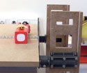
I attached a measuring tape with adhesive tape in that direction. The board, including the measuring tape, weighed approximately 1.3 kg. In this case, the center-of-gravity scale was calibrated before the board and the battery were placed across it. I then moved the 235-gram battery in small increments along the measuring tape. The position of the battery was determined by measuring along one of its long edges. I repeated these experiments with additional weights on the board and with the battery alone, by taring the board together with the weighing pan.
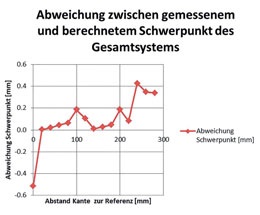
The position of the center of gravity (Figure 10) could be determined to within $±0.5$ mm. During longer measurement periods, the total weight drifted by up to 2 g, depending on the load. After removing the load, this deviation corrects itself after
in a few seconds. The measurement results show that the deviations are smaller in the middle of the 200-mm measurement range. Therefore, despite the installation effort, the option to adjust the center of gravity with a modified front plate should be utilized.
The center-of-gravity scale must be placed on a stable platform and be level both lengthwise and crosswise. No wind forces may act on the model; that is, measurements must be taken indoors.
Adjust the center-of-gravity scale to the model so that it lies horizontally on the scale
and the center of gravity to be measured is not at the edge of the measurement range.
Turn on the center-of-gravity scale and select the center-of-gravity mode. Once the calibration is complete, the model can be carefully placed on the scale (Figure 11) and aligned in both the longitudinal and transverse directions. This is a very important step for ensuring the reproducibility of the results! Wait until all vibrations have subsided, and then record the values.
The measurement is now essentially complete. However, it’s worth repeating the weighing process without the battery.
I have created an Excel spreadsheet to analyze the results. With electric models, the goal is usually to reposition the battery so that the target center of gravity is achieved. The weight and position of the battery, relative to the reference point, are calculated. A graph (Figure 12) illustrates this once the target and actual values have been entered. Once the battery has been repositioned according to the graph, the result can be verified with another measurement.
It has been shown that center-of-gravity measurements are highly reproducible when carefully aligned. The cross-levels purchased from a home improvement store are used to indicate the horizontal position of the base—
The frame and the weighing pan are not functioning properly and still need to be replaced. Of course, I measured my current models. In doing so, I did not find any significant deviations from the center of gravity previously determined using the seesaw or the three-scale method. The flexible, large-surface-area supports left no marks on the wings of the foam models. Even though I had to adjust the scale for the different models, the process was much faster, and the reproducible results give me greater confidence.
The achievable accuracy and reproducibility meet the requirements. The digital center-of-gravity scale differs from analog center-of-gravity scales in that it is easier to use and places less stress on the contact surfaces. The digital center-of-gravity scale can be easily used during construction, not only to determine the current position of the center of gravity, but also to measure the weight of a large component or to study the effect of the
components on the center of gravity. It is also possible to quickly assess whether a heavy battery leads to impermissible shifts in the center of gravity. Similarly, the influence of additional weights (ballast) or weight shifts (fuel level, longitudinally retractable landing gear) can be easily estimated. I wouldn’t want to be without my new digital center-of-gravity scale anymore.
Leonhard Keller
[1]. Stumpf, Rainer. Rainers Modellflugseite. Schwerpunkt und Einstellwinkel berechnen. [Online] http://www.rainers-modellflugseite.de/Schwerpunkt.html.
[2]. Meissner, Dietrich. Modellflug-Club Reichertshofen e.V. WinLaengs4. [Online] http://www.mfc-reichertshofen.de/index.php/know-how/2-uncategorised/281-winglaengs-beitrag.
[3]. Ranis, Frank. FLZ\_Vortex V1.217 (Demo-Freeware). FLZ\_Vortex. [Online] http://www.flz-vortex.de/flz_vortex.html.
[4]. GliderCG. GliderCG. [Online] https://glidercg.wordpress.com/.
[5]. Schwartz, Frank. Der digitale Schwerpunkt, Glider CG von Mahmoudi Modellsport. FMT. 2018, April.
[6]. Digitech Electronics BV. Tools. CG Wizard 3.0 Pro Version. [Online] http://www.digitech.nl/cg-wizard-pre-order-now.
[7]. XICOY Electronica SL. CG Meter. [Online] https://www.xicoy.com/catalog/index.php?cPath=57&osCsid=1f4ede21f06d117e7230f730471520a4.
[8]. Kallhovd, Olav. CG scale for F3X gliders. [Online] https://github.com/olka1/CG_scale.
[9]. natxopedreira. RC-Groups. CG scale geek way. [Online] https://www.rcgroups.com/forums/showthread.php?2917114-CG-Scale-geek-way.
[10]. Arduino. [Online] https://www.arduino.cc/.
[11]. Aliexpress. Aihasd Digital Load Cell Weight Sensor 2KG Portable Electronic Kitchen Scale + HX711 Weighing Sensors Ad Module for Arduino. [Online] https://www.aliexpress.com/item/Aihasd-Digital-Load-Cell-Weight-Sensor-2KG-Portable-Electronic-Kitchen-Scale-HX711-Weighing-Sensors-Ad-Module/32830560784.html.
[12]. SparkFun. SparkFun Load Cell Amplifier – HX711. [Online] https://www.sparkfun.com/products/13879.
[13]. Bodge. GitHub. An Arduino library to interface the Avia Semiconductor HX711 24-Bit Analog-to-Digital Converter (ADC) for Weight Scales. [Online] https://github.com/bogde/HX711.
[14]. reichelt elektronik. DEBO LCD 20X4 BL. [Online] https://www.reichelt.de/DEBO-LCD-20X4-BL3/index.html?ACTION=3&GROUPID=8244&ARTICLE=192144&START=0&OFFSET=16&.
[15]. fdebrabander. GitHub. Library for the LiquidCrystal LCD display connected to an Arduino board. [Online] https://github.com/fdebrabander/Arduino-LiquidCrystal-I2C-library.
[16]. maschinebau-fh.de. studienfächer. Statik-Kräftegleichgewicht und Momentengleichgewicht. [Online] http://www.maschinenbau-fh.de/s_gleichgewicht.html.


News from HEBU

TEAM MANAGER "THIS" BOSSHARD
 Rodito Nussbaumer

YOU KNOW WHAT I MEAN? 125 YEARS OF THE SWISS AERO CLUB
 Emil Giezendanner

PRIDE AND GOOD IDEAS
 Markus Nussbaumer

ATOM, THE NEW DOUBLE-DECKER FROM CPLR
 Matthias Bosshard

SUMMER FUN 2026 AT MG USTER
Martin Wunderli
F3A EUROPEAN CHAMPIONSHIPS IN ST-MACAIRE, FRANCE
Matthias Bosshard
52. 2026 ALPS CUP
Emil Giezendanner
HORIZON HOBBY/LEMACO NEWS: MICRO OV-10 BRONCO 645 MM BY E-FLITE

TWIN TOWN PARTNERSHIP
Wolfgang Voeller
CORSAIR F4U – A WARBIRD WITH A MEMORABLE LOOK
Jürgen Rosenberger, Jürgen Prinz
TRY-OUT DAY AT MFV WETTINGEN
Urs Keller
WELCOME, NEW MEMBER!
Andrea Bolliger
EURO CONTEST GLIDER ACRO TOUR AUSTRIA 2026

BY YOUTH, FOR YOUTH
Lorena Betschen
INSIGHTS INTO THE HISTORY OF SEAPLANES

SMALL, MODEL-LIKE SAILBOATS
Res Dauwalder
What's New at Leomotion.com

COUPE DES ALPES – OBSERVE AND LEARN
Rodito Nussbaumer
34th HAHNENMOOS ALPINE MODEL AIRPLANE CAMP
Res Dauwalder
FREE FLIGHT IN THE MIDDLE OF SUMMER
Urs Muntwyler
THE PC-21 STORY
Emil Giezendanner
NEWS FROM HEBU
 Julia Bucher

FROM 0 TO 100
Markus Nussbaumer
MEMORIES
Wolfgang Völler
NOS REGION – A HUB FOR ELECTRIC AVIATION
Emil Giezendanner
Have you almost forgotten about aircraft that take off and land vertically?
Emil Giezendanner
DO YOU KNOW WHAT I MEAN IN THE LAND OF SMILES?
Emil Giezendanner