
VINCENZO Rubber-Powered Model Car
For quite some time now, a small but active group of model airplane enthusiasts has been competing in the Wakefield competitions. Although there is keen interest in this category, new members rarely join the existing group. This unfortunate situation can be explained primarily by the fact that aspiring rubber-powered model airplane pilots struggle to acquire the necessary knowledge and experience.
Although he finds a few articles on the Wakefield class in the technical literature, each one deals with only a specific problem, and he has to piece them together into a coherent whole. This is a task that most people cannot manage. So his only option is to overcome these initial difficulties with the help of an experienced GM pilot. Unfortunately, this opportunity is available to only a few, since many Wakefield experts here are unable to pass on their knowledge. They build their models purely intuitively; development then proceeds based on observations.
So anyone who doesn’t find the right support when starting out in the GM category will soon give up due to perceived difficulties. It’s no surprise, then, that some people, disappointed, give up their hobby or even turn to building radio-controlled models. The difficulties mentioned are always the same and center on the construction and adjustment of the propeller head. This situation prompted me to release the Wakefield model “Vincenzo,” in which all parts related to the propeller can be made by the builder. For the propeller itself, a template for the underside can be provided, allowing the individual propeller blades to be bent without the tedious process of marking and carving. This way, anyone can use simple tools to fabricate a modern propeller head cleanly and precisely. For the fuselage, a drawn aluminum tube with a wall thickness of just 0.3 mm can be supplied, along with a pre-bent conical balsa tube. Since a certain level of building and flying experience is expected of anyone constructing this model, only the “Test Flight” chapter is described in particularly detail in the instructions. With Wakefield models, it is important to select the correct balsa wood for a specific design; otherwise, the model will be either too heavy or too weak. Therefore, the balsa wood should be selected with particular care according to the specifications in the parts list.
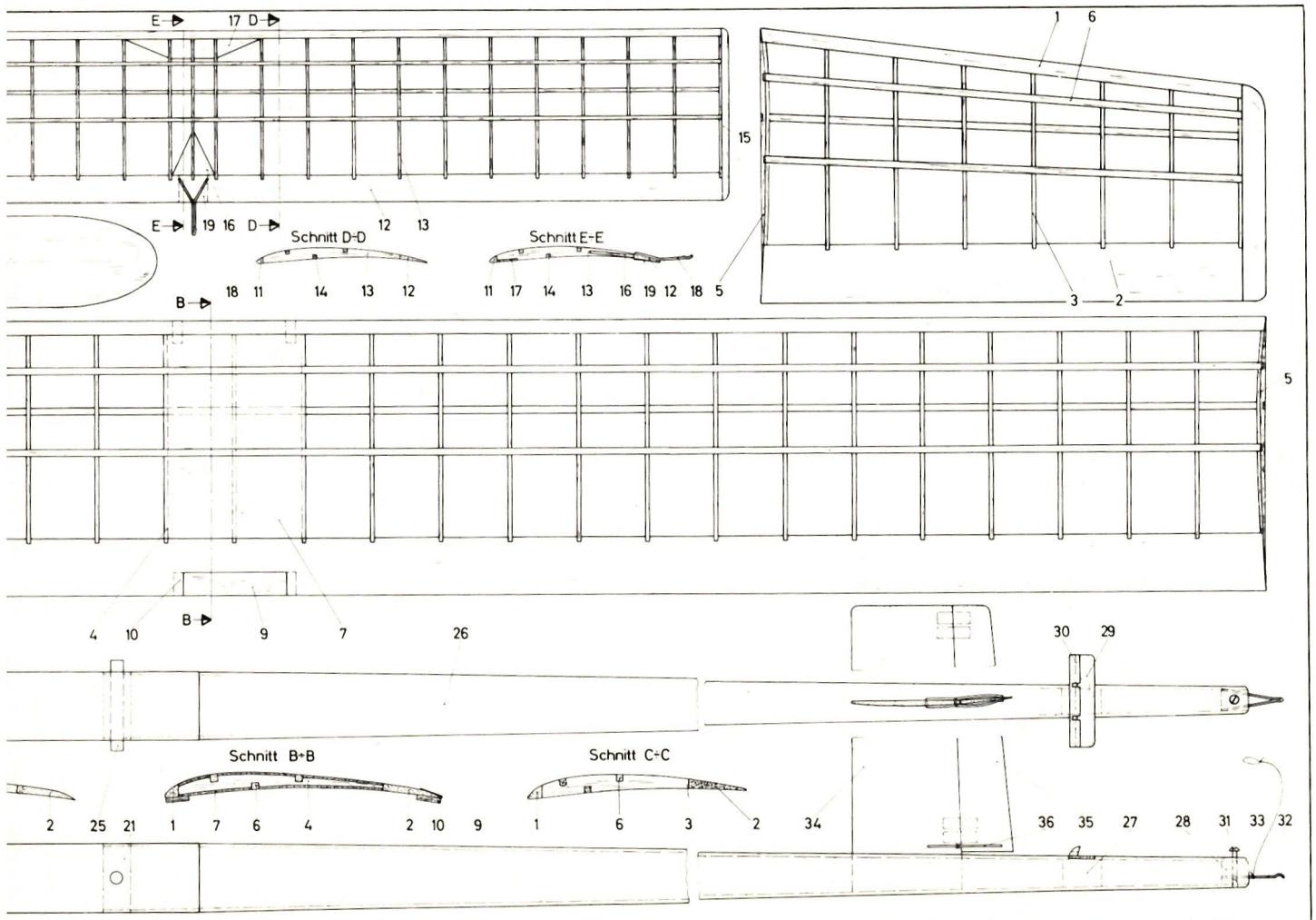
Assembly is carried out according to the previously marked-up construction plan, following the sequence of the individual part numbers. The end strips must be shaped and slotted beforehand. The wing tips are initially assembled into a rectangular shape. To prevent the lightweight frame from warping, use “Syncoll” or “Uhu coll” for gluing. The wingtips are attached so that the V-shape measures 120 mm. The ribs (3) are machined as a block to ensure a smooth transition from cut A:A to C:C. This simple method achieves an aerodynamic and geometric sweep that significantly improves flight stability, particularly during climb. The nose strips must be carefully sanded exactly according to the plan. Before covering the wings, all areas that will come into contact with the paper are painted. For all coats, the covering varnish is thinned. Mixing ratio of covering varnish to thinner: 1:1. Now we can apply the thin paper (12 g/m²) using covering varnish. To prevent warping, light colors should be preferred. To ensure the covering tightens evenly across the entire surface, the surfaces are moistened with water before painting. Afterward, the wing receives three to four light coats, and the elevator receives two light coats.
| Wingspan: | 129 cm |
| Wing area: | 15.2 dm² |
| Elevator area: | 34 dm² |
| Minimum weight: | 230 gr |
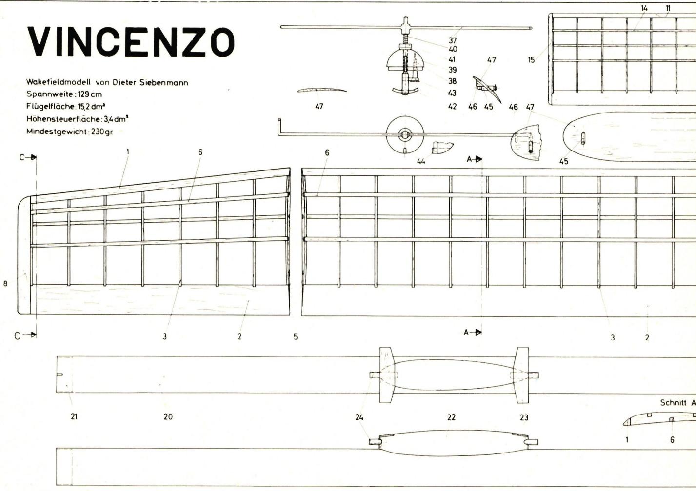
The aluminum rings are glued into the fuselage tube with Araldit, following the plan exactly. The holes for the dowels must be carefully marked and centered so that we can drill them exactly opposite each other in the center of the aluminum ring. Next, the conical balsa tube for the tailplane spar is glued together, taking care to ensure that no kink forms at the glue joint. The tailplane spar is then shaped so that it can be inserted into the aluminum tube, aligned precisely with the fuselage’s longitudinal axis, up to the ring. The balsa tube is now covered with fabric. Afterward, we can glue in the balsa blocks (27, 28), the tailplane mount, and the previously sanded-down side control. The tailplane spar is glued into the aluminum tube using Araldit. We sand the curve on the outside of the pylon onto the aluminum tube, which we have previously wrapped with glass paper. The finished pylon is not glued in place just yet. The entire rear fuselage section and the pylon are now given two to three coats of primer. Finally, the screw (31) is screwed in and the hook (32) is glued into place.
Using a plywood template, the propeller blades (47) are cut out, then soaked in water, coated with Syncoll, and tied over the plaster mold to dry. Once the blades have dried thoroughly on the mold, they can now be shaped, checking the blade parting lines against the dashed lines on the plan. Next, we cover the propeller with paper (12 g/m²). To ensure the blades retain their exact angle and profile, we should secure them over the plaster mold for a while after each coat. The brass tubes (45) can be glued in at exactly the correct angle using the jig shown in Fig. 1. The boom wire (37) is bent according to the plan and cut to the appropriate length. Next, file the notches that will hold the wheel locks. Now we can glue in the steel wires (42, 43) and bend the lower one according to the plan. A slot is drilled and filed into the front block (38), and the front plate (44) is glued in place. Finally, we check the propeller’s pitch angle using a template made according to Fig. 2. Any deviations are corrected by carefully twisting the propeller spindle wire with the propeller blade removed. This work should be performed very carefully, as the propeller’s efficiency depends heavily on it.
The elevator is secured with two rubber rings, which are stretched over the hooks (18) from underneath the fuselage, thereby simultaneously holding the mounting thread (33) in place; this thread should be sized to allow for a 45° deflection. The slot for the plate (44) is filed into the fuselage so that the extension wire (37) is parallel to the elevator when viewed from the front. Now we glue the pylon (22) to the fuselage using Araldite. The elevator should be parallel to the wing, and the center of gravity should be at 60%. To ensure consistent flight characteristics, the wing must be aligned perpendicular to the fuselage and held in this position with four stops (10).
To stretch the rubber, we’ll use a hand drill, which should have a gear ratio of 1:4 to 1:6. The hook shown in Fig. 3 is bent from 2-mm steel wire and glued into the drill chuck with Araldite. This prevents the hook from coming loose unexpectedly, thereby protecting the assistant from potential injury. We also need a ramrod (Fig. 4), which allows us to easily replace the rubber band, and the cleaning rod shown in Fig. 5, which is used to wipe the lubricant squeezed out by the rubber band from the hull wall.
Since the rubber’s properties can vary greatly from one shot to the next, you should always use the same rubber for a new model. This requires 1–1.5 kg. To ensure the rubber does not lose quality during storage, it must be kept in an airtight, dark plastic bag in a cool place. If possible, you should fly with a single piece of rubber only once a day. It is therefore recommended to prepare approximately 10 strands. Since a difference of just 0.1 mm already represents a 10% change in length, no exact specifications regarding the number of threads or cross-sectional area can be provided. As a rule of thumb, the length of the finished strand should be 56–59 cm. It does not matter whether this is achieved with 14–16 strands of 1x6 mm or with 20–24 strands of 1x4 mm. Since the rubber band becomes slightly longer during the winding process, it should measure 54–57 cm beforehand. For obvious reasons, no exact specifications can be given regarding the winding count; it should be around 400 turns. The best way to determine this is to wind two strands up to the breaking point and, during flight operation, use only 90% of those turns. Weigh out 38 g of rubber per strand. Wipe off the talcum powder with a clean cloth. Castor oil is best used as a lubricant. Lightly lubricate the ends of a rubber strand and tie them with a double knot followed by three single knots. The protruding ends are trimmed to a length of 10–15 mm. Now we rub the lubricant vigorously into all the rubber strands. One day later, the breaking-in process can begin. To do this, we stretch the prepared rubber bands three times for 5 seconds each, extending them to 6–7 times their original length. It’s important to note that the rubber should be allowed to rest for some time after each intense stretch; otherwise, it will suffer a significant loss of quality. Over the following days, the rubber bands are stretched to 40%, 60%, and 80% of their maximum length, respectively. The entire rubber band treatment process thus takes one week. In return, the 10 treated rubber bands allow for a total of approximately 100 launches. The rubber’s enemies are sunlight, dirt, heat, and cold. You should therefore store the rubber in an airtight, sealable container during competitions.
First, check the wings and elevator for any warping, which can be corrected by twisting them in opposite directions over a hot plate. The right half of the wing (as viewed from the rear) should be set at a 1–2 mm greater angle. The propeller’s thrust direction should point 30°–1° to the right. To achieve this, approximately 0.4 mm must be filed away on the right side. Now the rubber band can be attached to the propeller head. To do this, place half of each end of the rubber band over the ends of the hook (42) and secure them with a small rubber ring. Hook the other end of the rubber band—with the knot—into the fuselage using the loading rod. The propeller (39) must be adjusted so that the propeller stops with a reserve of 10 revolutions. In gliding flight, the model should fly a right turn. If it turns out that the maximum fin deflection specified in the plan is insufficient for this, a corresponding drag flap must be glued under the right wing root. This prevents the model from crashing in a right-hand spiral shortly after takeoff in gusty weather.
For the first launch, wind the rubber band approximately 100 revolutions and release the model at an angle of 5–10° to the right of the wind direction. It should then perform a shallow climb in a right-hand turn. Any deviations from this flight pattern can be corrected by adjusting the pull axis. Now we increase the winding count until 90% is reached. To achieve optimal flight performance—that is, maximum flight performance with sufficient safety—we must conduct several test flights at this winding count. To do this, the motor pull axis is directed upward and to the right until the model flies right on the edge between a right-hand spiral dive and a stall. With this trim, the model would, of course, only be competitive in calm air; so, in order to be able to fly in any weather, the thrust axis must be adjusted back to the lower left by approximately 20' or 0.1–0.2 mm. To verify this, fly the model in gusty conditions. This will reveal whether a minor correction is necessary. With a model tuned in this way, the climb begins nearly vertically and in a tight right-hand spiral. As the torque decreases, the climb becomes steadily flatter until the model reaches an altitude of about 60 m after 35 seconds of climb time. The glide time is 25 minutes. However, this performance can only be maintained if the model is periodically checked for warping. I wish everyone lots of fun and success flying the Vincenzo.
Wings
| 1 | 3 | Nose strip | Medium-light balsa | 6 x 6 |
| 2 | 3 | Wing tip | Light balsa, square, large | 3 |
| 3 | 32 | Rib | Lightweight balsa, square, large | 1.5 |
| 4 | 3 | Rib | Medium balsa | 1.5 |
| 5 | 4 | Rib | Medium balsa | 1.5 |
| 6 | 9 | Stringer | Hard balsa | 3 x 3 |
| 7 | 4 | Planking | Medium balsa | 1 |
| 8 | 2 | Edge block | Light balsa | 10 x 10 |
| 9 | 1 | Reinforcement | Plywood | 0.8 |
| 10 | 4 | Stop block | Beech | 5Ø |
Height adjustment
| 11 | 1 | Nose spar | Lightweight balsa | 3 x 3 |
| 12 | 1 | Rib | Lightweight Balsa, square, large | 2 |
| 13 | 25 | Rib | Lightweight balsa | 1 |
| 14 | 3 | Stringer | Hard balsa | 1.5 x 1.5 |
| 15 | 2 | Edge block | Light balsa | 3 |
| 16 | 2 | Reinforcement | Lightweight Balsa | 2 |
| 17 | 1 | Reinforcement | Medium balsa | 1 |
| 18 | 1 | Hook | Steel wire | 1Ø |
| 19 | 1 | Reinforcement | Plywood | 0.8 |
Fuselage
| 20 | 1 | Tube | Aluminum | 30Ø |
| 21 | 2 | Ring | Aluminum | 29.4Ø |
| 22 | 1 | Pylon | Lightweight balsa | 25 x 25 |
| 23 | 2 | Support | Plywood | 1.5 |
| 24 | 2 | Dowel | Beech | 5Ø |
| 25 | 1 | Anchor | Aluminum | 6Ø |
| 26 | 1 | Tube | Lightweight balsa | 1.5 |
| 27 | 1 | Block | Lightweight balsa | |
| 28 | 1 | Block | Lightweight balsa | |
| 29 | 1 | Layer | Plywood | 1.5 |
| 30 | 1 | Stop | Medium balsa | 5 x 5 |
| 31 | 1 | Screw | Brass | M 2/15 |
| 32 | 1 | Hook | Steel wire | 1Ø |
| 33 | 1 | Boundary cord | Nylon | 0.5Ø |
| 34 | 1 | Side control | Lightweight balsa, square, large | 3 |
| 35 | 1 | Fin | Lightweight balsa, square, large | 3 |
| 36 | 1 | Wire | Brass | 1Ø |
Propeller head
| 37 | 1 | Boom | Steel wire | |
| 38 | 1 | Front block | PVC | |
| 39 | 1 | Screw | Steel | |
| 40 | 1 | Spring | Steel | |
| 41 | 1 | Ball bearing | Steel | |
| 42 | 1 | Hook | Steel wire | 2Ø |
| 43 | 1 | Latch | Steel wire | 2Ø |
| 44 | 1 | Plate | Aluminum | 1.5 |
| 45 | 2 | Tubes | Brass | 3 x 10 |
| 46 | 2 | Stop | Plywood | 1.5 |
| 47 | 2 | Propeller blade | Medium balsa | 1 |


News from HEBU

TEAM MANAGER "THIS" BOSSHARD
 Rodito Nussbaumer

SUMMER FUN 2026 AT MG USTER
Martin Wunderli
BY YOUTH, FOR YOUTH
Lorena Betschen
SMALL, MODEL-LIKE SAILBOATS
Res Dauwalder
TRY-OUT DAY AT MFV WETTINGEN
Urs Keller
What's New at Leomotion.com

52. 2026 ALPS CUP
 Emil Giezendanner

ATOM, THE NEW DOUBLE-DECKER FROM CPLR
 Matthias Bosshard

INSIGHTS INTO THE HISTORY OF SEAPLANES

YOU KNOW WHAT I MEAN? 125 YEARS OF THE SWISS AERO CLUB
Emil Giezendanner
34th HAHNENMOOS ALPINE MODEL AIRPLANE CAMP
Res Dauwalder
CORSAIR F4U – A WARBIRD WITH A MEMORABLE LOOK
Jürgen Rosenberger, Jürgen Prinz
F3A EUROPEAN CHAMPIONSHIPS IN ST-MACAIRE, FRANCE
Matthias Bosshard
HORIZON HOBBY/LEMACO NEWS: MICRO OV-10 BRONCO 645 MM BY E-FLITE

PRIDE AND GOOD IDEAS
 Markus Nussbaumer

EURO CONTEST GLIDER ACRO TOUR AUSTRIA 2026

FREE FLIGHT IN THE MIDDLE OF SUMMER
Urs Muntwyler
THE PC-21 STORY
Emil Giezendanner
TWIN TOWN PARTNERSHIP
Wolfgang Voeller
WELCOME, NEW MEMBER!
Andrea Bolliger
COUPE DES ALPES – OBSERVE AND LEARN
Rodito Nussbaumer
NEWS FROM HEBU
 Julia Bucher

FROM 0 TO 100
Markus Nussbaumer
MEMORIES
Wolfgang Völler
NOS REGION – A HUB FOR ELECTRIC AVIATION
Emil Giezendanner
Have you almost forgotten about aircraft that take off and land vertically?
Emil Giezendanner
70 YEARS OF THE NIDWALDEN MODEL AIRPLANE CLUB
Martin Barmettler