
Slow on the uptake?
Wiring for Multi-Motor Models
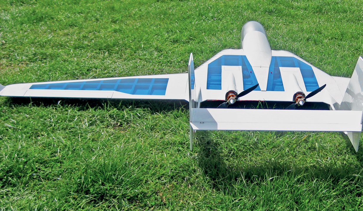
Usually, it’s all straightforward: the motor at the very front, then the electronic speed controller (ESC), and the battery further back. For conventional models, this “layout” works well, and the specified cable length is usually sufficient. But what do you do if a model looks completely different—perhaps because it has multiple motors or the battery needs to be placed somewhere else entirely for center-of-gravity reasons? In nearly all such cases, at the very least, the cables will need to be extended.
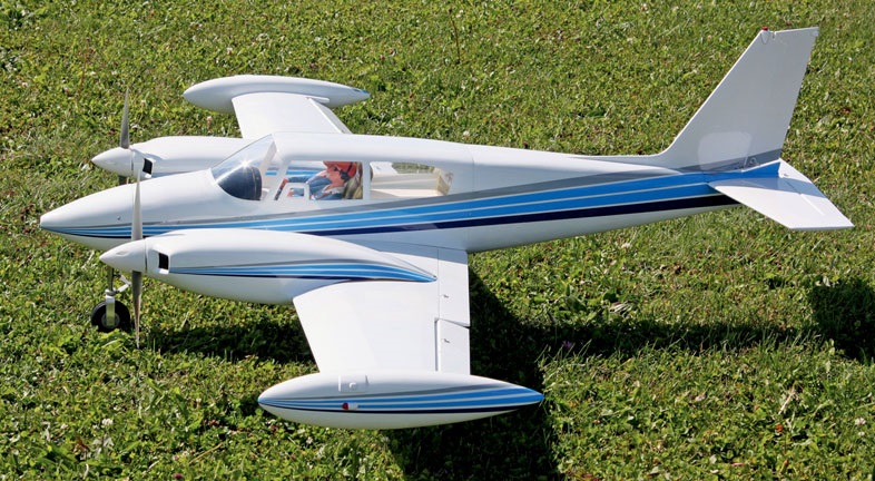
Now begins the series of awkward uncertainties: What effect does such an extended cable have? Does it perhaps draw a lot of power? Does it interfere with the remote control functions? Does it matter whether the cables are extended before or after the speed controller? With multi-engine aircraft, sooner or later you’ll face the question of whether a separate
ESC for each motor. And if you’re using BEC controllers: Can the built-in power supplies be combined without any issues? Well, let’s take it one step at a time.
The battery supplies a DC voltage. This can be used to make wires glow and light up semi-
crystals to glow, but at best, it will only move motors a short distance. To keep them running continuously, a timely polarity change (commutation) is required. This is one of the controller’s many tasks. And since
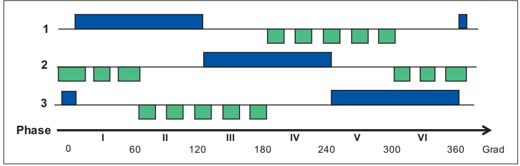
model aircraft today almost exclusively use three-phase controlled motors, the battery’s DC voltage must first be converted into rotating-field pulses. This means that the input voltage supplied via the positive and negative cables is distributed across three cables at the ESC output.
This does not mean, however, that the three wires are now constantly supplied with only two-thirds of the input current. Rather, on the output side, there are always only two cables carrying the positive and negative currents, but they alternate in a cyclical pattern. Incidentally, the frequency of these switching operations remains within a very manageable range in our model-sport applications. A 2-pole motor completes just 200 commutation cycles at 12,000 revolutions per minute (RPM). However, since the motors are not always meant to run at full “throttle,” the alternating voltage pulses are interrupted by pauses of varying lengths. This is known as pulse-width modulation (PWM). The pulse-to-pause ratio creates the effect of varying the voltage (speed control). This occurs much faster than commutation—typically at 8 kilohertz (kHz). Low-inductance motors even require 16 or 32 kHz,
in order to operate efficiently at reduced speed.
The Problem with Harmonics However, both commutation and PWM result in the voltage being switched on or off abruptly. This generates harmonics that can be many times the fundamental frequency and thus fall within the range of radio waves. Back when RC systems still operated in the shortwave range (27, 35, or 40 MHz), this could certainly cause interference. In the era of 2.4-GHz systems, this problem has significantly
. Nevertheless, it is still recommended to route all three wires between the ESC and the motor close together so that the generated magnetic fields cancel each other out. The easiest way to achieve this is by twisting them slightly (!) together. However, even here, there are limits. If the cable length between the controller and the motor is too long, the commutation signal can become “blurred.” For this reason, cable lengths of approximately 70 cm should not be exceeded here either. From an energy efficiency standpoint, it makes no sense that some
controllers are equipped with thinner cables on the output side than on the (battery) input side. Because, as already mentioned, the current in the wires leading to the motor is not lower; it can actually become higher at “partial throttle” because a free-wheeling current generated by the PWM is added. However, the power losses (Pv) in the cables increase quadratically with the instantaneous current (I), so it makes no sense to further increase the resistance (R) by using thinner cables (Pv = I² * R). Although the average current over time is lower (because one of the three cables is repeatedly
(takes a “break”), but that’s not the key point here. This would make sense if the current density in the cables reached such high levels that there was a risk of the insulation melting. But we’re still a long way from that in electric flight. For the sake of completeness, it should be noted that the straight, current-free wire is not entirely without function, as it carries the signal necessary for commutation, which tells the ESC the rotor position and thus the correct timing for commutation. From an energy perspective, however, this signal transmission plays no role.
This makes it clear that the cable extension between the ESC and the brushless motor must not be made using lightweight, thin-wire technology, especially since three cables are needed on this side instead of two. Although the interference potential generated by harmonics is generally filtered out by modern 2.4-GHz receivers, in extreme cases it can still cause interference with other components of the onboard system. Therefore, motor cables should not run
long in parallel with RC connection cables—and certainly not in the same cable harness.
Thus, everything seems to point toward extending—if necessary—the cable run between the battery and the ESC. But as always, when a solution seems too simple, physics likes to throw a wrench in the works. In this case, that’s because the voltage on the battery line is no longer pure DC; due to the speed controller’s previously mentioned “chopping” activity, an AC voltage is superimposed on it. These are voltage spikes that the electronics don’t necessarily like. Filtering them out
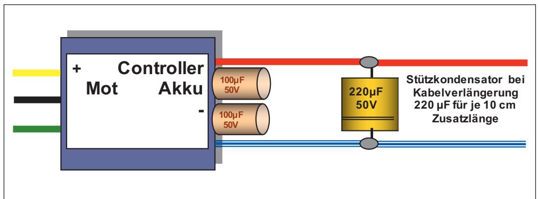
is primarily the task of the battery, which, incidentally, also acts as a capacitor of considerable size. Because its connection via cables of varying lengths and connectors that are not always optimal raises concerns, every speed controller is equipped with capacitors on the input side that relieve the battery of AC current. If, due to long battery cables, this division of labor becomes increasingly uneven at the expense of these capacitors, they may become overloaded. Therefore, it is necessary to relieve the load on them with parallel support capacitors when cable lengths are increased. It makes sense to solder the additional capacitors right at the extension point, where soldering is required anyway. Approximately 220 µF per 10 centimeters of extension is recommended. It is often advised to ensure that so-called switching-rated electrolytic capacitors (with a low ESR value) are used. For individual consumers, however, it may not be easy to obtain the relevant data sheets. Therefore, here’s a tip: Two smaller capacitors in parallel are often better than one large one (2 × 220 µF instead of 470 µF). Standard speed controllers are equipped accordingly. It goes without saying that the capacitors must have the correct voltage rating.
When extending the battery connection, even on multi-motor aircraft, it is possible to place the ESC directly near the motor, which usually also improves cooling.
Speed controllers are often more expensive than the motors they power. That’s why, in multi-motor systems, the question often arises as to whether a single controller could “power” multiple motors at the same time. Yes, it can—provided that...! With brushless motors, however, only parallel connection works. The higher current demand of the multi-motor system is the lesser problem here, provided, of course, that the ESC can handle the total current (plus a small safety margin). The challenge here lies with the control line—the one of the three wires that transmits the commutation information. All motors must deliver the same signal at the exact same time. This inevitably means: All motors run absolutely in sync… or not at all. To ensure they run synchronously with reasonable efficiency, all motors should have as close to the exact same specific rotational speed (k_v or n_spec) as possible (it’s good to assume, but better to measure!) and, of course, be driven by propellers of the same size. Even in a three-engine aircraft (Ju 52), this principle worked flawlessly.
Most commercially available ESCs designed for the typical operating range of 2s to 6s LiPo batteries have a built-in receiver power supply—known by the acronym BEC (Battery Eliminator Circuit). It provides a constant voltage of around 5 V (sometimes higher values up to 8.5 V can be set) to power the receiver system. If you’re willing to spend a little more, you can also get ESCs with an HV-BEC, which are compatible with batteries up to 12s. The conventional wisdom here is: Use only one BEC and disable the other by disconnecting the positive wire! This wastes resources. It is therefore not wrong to use both systems by decoupling the positive wires from each other using looped-in Schottky diodes, since this prevents current from flowing from one side to the other. Unfortunately, this isn’t entirely ideal either, because servo motors not only consume current but also generate it under very specific conditions. Such reverse current pulses—which, due to the diodes’ valve effect, can no longer flow out—can cause processor-controlled RC receivers to boot up and restart, which, since it happens during flight,
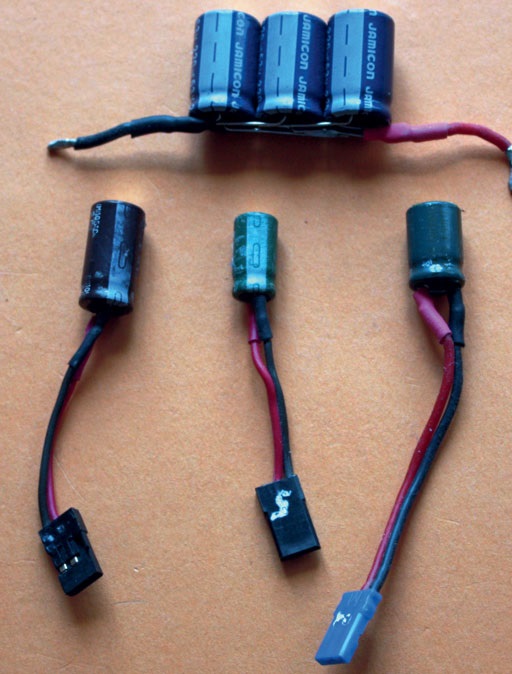
is not subject to entertainment tax. But don't worry—here, too, “a capacitor ranging from 2 to 3 times 220 µF up to 470 µF/10 V will save the day.”
And for once, the rule is: the more, the better!
Incidentally, buffer capacitors in the receiver circuit have also proven their worth many times over when it comes to other sources of interference.
It’s a bold move, but by no means reckless, to simply connect both BEC positive terminals directly. Prerequisite: Both systems are turned on and off simultaneously and supply
to within about 10 millivolts (mV) (e.g., 5.42 and 5.43 V)—which is not unusual for modern production models. An
An additional capacitor won’t hurt here either.
Text and images:
Ludwig Retzbach


News from HEBU

TEAM MANAGER "THIS" BOSSHARD
 Rodito Nussbaumer

SUMMER FUN 2026 AT MG USTER
Martin Wunderli
TRY-OUT DAY AT MFV WETTINGEN
Urs Keller
52. 2026 ALPS CUP
 Emil Giezendanner

ATOM, THE NEW DOUBLE-DECKER FROM CPLR
 Matthias Bosshard

INSIGHTS INTO THE HISTORY OF SEAPLANES

YOU KNOW WHAT I MEAN? 125 YEARS OF THE SWISS AERO CLUB
Emil Giezendanner
34th HAHNENMOOS ALPINE MODEL AIRPLANE CAMP
Res Dauwalder
CORSAIR F4U – A WARBIRD WITH A MEMORABLE LOOK
Jürgen Rosenberger, Jürgen Prinz
SMALL, MODEL-LIKE SAILBOATS
Res Dauwalder
F3A EUROPEAN CHAMPIONSHIPS IN ST-MACAIRE, FRANCE
Matthias Bosshard
What's New at Leomotion.com

HORIZON HOBBY/LEMACO NEWS: MICRO OV-10 BRONCO 645 MM BY E-FLITE

PRIDE AND GOOD IDEAS
 Markus Nussbaumer

BY YOUTH, FOR YOUTH
Lorena Betschen
FREE FLIGHT IN THE MIDDLE OF SUMMER
Urs Muntwyler
THE PC-21 STORY
Emil Giezendanner
TWIN TOWN PARTNERSHIP
Wolfgang Voeller
EURO CONTEST GLIDER ACRO TOUR AUSTRIA 2026

WELCOME, NEW MEMBER!
Andrea Bolliger
COUPE DES ALPES – OBSERVE AND LEARN
Rodito Nussbaumer
NEWS FROM HEBU
 Julia Bucher

FROM 0 TO 100
Markus Nussbaumer
MEMORIES
Wolfgang Völler
NOS REGION – A HUB FOR ELECTRIC AVIATION
Emil Giezendanner
Have you almost forgotten about aircraft that take off and land vertically?
Emil Giezendanner
70 YEARS OF THE NIDWALDEN MODEL AIRPLANE CLUB
Martin Barmettler