
Outdoor Flamingo
The Udet Flamingo model is a classic from Aeronaut and first appeared in the well-known manufacturer’s lineup in the early 1970s. Until recently, the model was sold with virtually no changes. To mark Aeronaut’s 100th anniversary, the Udet Flamingo underwent a complete redesign. The model is now assembled entirely from laser-cut parts, and a 35-mm electric motor has replaced the combustion engine as the power source.
Both the construction technique and the components are now state-of-the-art, allowing for very simple assembly using a snap-fit system. A particularly
original is the radial engine mock-up, which consists of laser-cut parts. This gives the model a very realistic appearance. In addition to optimizing the wing design, the model has been equipped with ailerons.
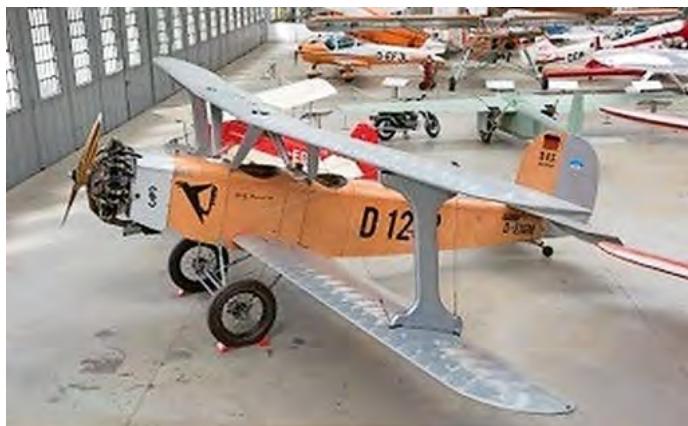
The U12, a Monday-morning prototype, was developed under the direction of chief designer Hans Henry Herrmann at Udet Flugzeugbau GmbH in 1925. The U12 was widely used as a training aircraft and enjoyed great popularity among flight schools and students of the time, such as Heinz Rühmann, Elly Beinhorn, and Thea Rasche. At the Schleissheim Commercial Pilot School, too,
the Flamingo was the standard training aircraft. Ernst Udet, who was a co-owner of the aircraft company, flew the Flamingo—painted red and bearing the registration D 822—with great success during his international aerobatic demonstrations. One maneuver that is still famous today was picking up
a “handkerchief” from the ground as he flew past. The Flamingo was built using a wooden airframe covered with fabric, in keeping with the state of the art at the time. It was powered by a seven-cylinder Siemens-Halske Sh11 radial engine producing 96 PS. A flyable replica of the
The model is delivered as a classic model kit with many small boards and strips, as well as a wide range of accessories. The individual parts for the fuselage, tail unit, and wings are laser-cut and neatly packaged by assembly group in plastic sleeves. Before assembly, you’ll need to cut them out of the frames and lightly sand them down. The comprehensive assembly instructions provide step-by-step guidance on each stage of construction, along with the materials required for each.
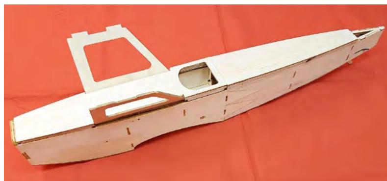
We'll start by building the fuselage. The fuselage sidewalls consist of a combination of poplar plywood and balsa wood, with the plywood used in the forward section of the fuselage. This is also where the battery mount and servo board are located; they are also made of poplar plywood.
In the rear section of the fuselage, which is made of balsa wood, the structural frames are inserted and glued in place with white glue. It should be noted here that all gluing is done using white glue. It offers high strength combined with low weight. After curing, it remains elastic, making it an ideal adhesive for the stresses encountered during flight.
After joining the two fuselage side sections, reinforcing strips are glued to the underside of the fuselage. They are used in the area of the wing cutout and the motor mount. Actually, the canopy struts should be glued in place at this point. However, it is advisable to postpone this step until later. On the one hand, this makes it easier to shape the fuselage; on the other hand, it also simplifies the installation of the servos for the elevator and rudder. Next, continue with the construction of the fuselage cover. It consists of a frame that is covered with skin. The frame
is first secured to the fuselage with adhesive tape and then covered with skin. The upper rear section of the fuselage is also skinned during this same step. Before the lower part of the fuselage is covered with skin, the two Bowden cables must be installed. This completes the work on the fuselage for now, and we can turn our attention to assembling the tail unit.
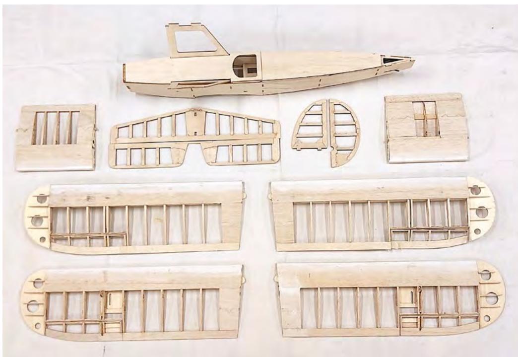
The model is built using a slat-and-rib construction method with 5-millimeter balsa wood. Since the individual parts
already be the correct length and the nose end strip is grooved, no construction plan is needed as a guide. You can assemble the model directly on a flat workboard covered with plastic sheeting. The two rudder halves can be assembled using the same principle. Two 5x3 mm pine strips are used to join the two halves.
The Udet Flamingo kit features a multi-piece wing assembly. It consists of the upper and lower wing center sections, as well as the upper and lower wing sections. One advantage of Aeronaut’s construction method is that, according to the instructions, the individual elements simply need to be joined together. As a result, the individual wing components come together quite naturally. All you need is a flat surface; there’s no need to pin a plan to it. The assembly itself goes very quickly, and you make rapid progress. However, you need to be careful when using the individual ribs and pay close attention to their labels. At first glance, they all look the same, but they serve different functions. For example, some are designed to hold the torsion pin, while others are for the aileron servo. You need to be careful with the wing, as this is the root rib and must be inserted at an angle.
must. A template would be helpful here to ensure that all four wing sections have the same angle. It’s best to make one yourself. This ensures the correct angle of attack between the fuselage or canopy and the wing for all four wing halves. For the outer edge arch, it is recommended to insert ribs made from scrap material between the last rib and the edge arch. These prevent the plastic film from sagging during the later covering process. After applying the upper and lower skin and the rib
, one wing half is complete. The steps described above must be repeated for the three remaining wing sections. Finally, the slots, including the servo frames for the ailerons, are installed on the two lower wing sections. At this point, it is advisable to run the cables for controlling the servos right away, as this is not quite as easy once the frame film has been applied. The aileron process also includes cutting out and encasing the ailerons on all four wing halves.
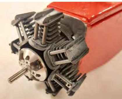
Assembling the engine mockup can actually be considered a kit in its own right. It’s therefore not surprising that all the individual parts are included in the Flamingo kit, packaged separately. Assembly begins by gluing the two ring frames together. The seven cylinder head bases are mounted on these frames, into which the cylinder towers—along with their ribs—are then inserted. Next, the push rods are attached to the front, and the respective cylinder head covers are placed on top of the cylinders. Once the electric motor has been mounted on the head frame, the engine mockup can be adjusted. This is where two shims come into play, which allow for precise alignment of the mockup with the head frame. Finally, check to ensure that the external rotor drive can move freely and does not rub against any part of the mock-up. The motor mock-up is permanently secured using two M15 screws.
First, they begin by covering the individual components with iron-on film. Alternatively, fabric can also be used for the covering.
In our case, we are using Oracover iron-on film. Following templates found online, the Udet Flamingo is covered in red and silver. The corresponding markings and lettering come from an aviation enthusiast who has a good source for plotter prints. Once the covering work is complete, the individual components can be assembled. In the first step, a 3-millimeter beech dowel is inserted into the front section of the upper fuselage cover, and two magnets are attached to the rear. These hold the fuselage cover in place during flight.
In the next step, the lower and upper wing center sections are attached to the fuselage. The lower wing center section is glued into the fuselage cutout. Be sure to center it so that it protrudes equally on both the left and right sides of the fuselage. Care must also be taken to center the upper wing center section and ensure that it lies flat and is not twisted. The elevator and rudder are attached to the stabilizer using adhesive tape—
| Wingspan: | approx. 1,310 mm |
| Fuselage length: | approx. 910 mm |
| Flight weight: | starting at approx. 1,650 g |
| Wing area: | approx. 50 dm² |
| Wing loading: | approx. 37 g/dm² |
| Propeller: | CAMcarbon Light Prop 12×6" |
Strike. Make sure the oars can move freely. If necessary, a little adjustment
At this point, you can also connect the two rudders to the linkage.
Next, the main landing gear, including the wheels, is installed or assembled. The kit includes a cardboard template for making the wheels, which you use to create the tires. To do this, cut the neoprene strips to the length specified in the instructions, place them in the template, and secure them with superglue. The cut should be made along the flattened part of the template. Be careful when cutting the neoprene strips, as
you’ll get a straight cut. It’s better to cut off a little extra here and then trim it down to ensure a clean cut. Once the glue has hardened, the tire can be mounted onto the rim and secured with superglue. The main landing gear consists of pre-bent landing gear legs made of steel wire. They are inserted into the grooves provided for this purpose on the underside of the fuselage and centered. The grooves are then closed by the landing gear mount.
Once all work on the four wing halves and the center section is complete, assembly can begin. Small插管 ensure a stable connection; the wing halves are slid onto these and secured with adhesive tape. Now the two outer struts can be installed, and the linkage rods for operating the upper ailerons can be attached. The exact procedure for these steps is described in detail in the assembly instructions. The final step is installing the cockpit canopy, which is also included in the kit. If you like, you can add a suitable pilot figure to the cockpit. Once you’ve installed the individual receiver and programmed the functions, you’re ready to head out to the model airfield for your first flight.
This year’s mild winter months allowed for almost continuous flying at the model airfield. As a result, the first flights with the Udet Flamingo took place in early March. It performed exactly as expected: it flew effortlessly—and very well at that. The Flamingo handles superbly in the air, and the power unit recommended by Aeronaut delivers plenty of power.
P.S.: We’re still working on the “handkerchief pickup” maneuver...


TEAM MANAGER "THIS" BOSSHARD
 Rodito Nussbaumer

F3A EUROPEAN CHAMPIONSHIPS IN ST-MACAIRE, FRANCE
 Matthias Bosshard

News from HEBU

YOU KNOW WHAT I MEAN? 125 YEARS OF THE SWISS AERO CLUB
 Emil Giezendanner

SUMMER FUN 2026 AT MG USTER
Martin Wunderli
TRY-OUT DAY AT MFV WETTINGEN
Urs Keller
52. 2026 ALPS CUP
Emil Giezendanner
BY YOUTH, FOR YOUTH
Lorena Betschen
ATOM, THE NEW DOUBLE-DECKER FROM CPLR
Matthias Bosshard
CORSAIR F4U – A WARBIRD WITH A MEMORABLE LOOK
Jürgen Rosenberger, Jürgen Prinz
SMALL, MODEL-LIKE SAILBOATS
Res Dauwalder
What's New at Leomotion.com

TWIN TOWN PARTNERSHIP
Wolfgang Voeller
EURO CONTEST GLIDER ACRO TOUR AUSTRIA 2026

INSIGHTS INTO THE HISTORY OF SEAPLANES

34th HAHNENMOOS ALPINE MODEL AIRPLANE CAMP
Res Dauwalder
HORIZON HOBBY/LEMACO NEWS: MICRO OV-10 BRONCO 645 MM BY E-FLITE

COUPE DES ALPES – OBSERVE AND LEARN
Rodito Nussbaumer
PRIDE AND GOOD IDEAS
 Markus Nussbaumer

FREE FLIGHT IN THE MIDDLE OF SUMMER
Urs Muntwyler
THE PC-21 STORY
Emil Giezendanner
WELCOME, NEW MEMBER!
Andrea Bolliger
NEWS FROM HEBU
 Julia Bucher

FROM 0 TO 100
Markus Nussbaumer
MEMORIES
Wolfgang Völler
NOS REGION – A HUB FOR ELECTRIC AVIATION
Emil Giezendanner
Have you almost forgotten about aircraft that take off and land vertically?
Emil Giezendanner
70 YEARS OF THE NIDWALDEN MODEL AIRPLANE CLUB
Martin Barmettler