
Geodetic wing construction for a lightweight glider model
Building your own model airplane isn't the easiest or fastest way to get a new one, but for a small group of model airplane enthusiasts, it's still the most appealing option. In this report, I’d like to describe the process of building a small, lightweight, and easy-to-handle electric glider from scratch, with a particular focus on a somewhat unconventional wing construction method used in the project.
The goal was to create a lightweight glider that could fit in a backpack and had a correspondingly low wing loading. The primary focus was therefore on a low sink rate; the glide ratio was not the main priority here. Lightweight construction is widely used in the currently very popular F3K, F3-RES, F3J, and F5J classes, where models are in demand that can still take advantage of even weak or tight thermals.
I had envisioned the following key specifications:
Flight weight: < 500 g
Wingspan: approx. 1.5 m
Controls: elevator, rudder, air brakes
3-piece wing with double V-bend; V-tail
Fuselage nose section made of fiberglass-reinforced plastic (FRP), tail tube made of carbon-fiber-reinforced plastic (CFRP)
My initial thoughts focused on the construction of the wings and tail. The classic balsa-planked spar construction didn’t seem light enough to me, and experience has shown that without planking, one would have trouble achieving sufficient torsional rigidity. Carbon-tube-spar wings are currently widespread, but it didn’t really seem interesting to me to design a model based on that construction method—
for which there are already dozens of kits and ready-made models available for purchase. So I turned to a construction method that, while not new, has fallen somewhat out of favor in recent decades: the geodesic rib construction
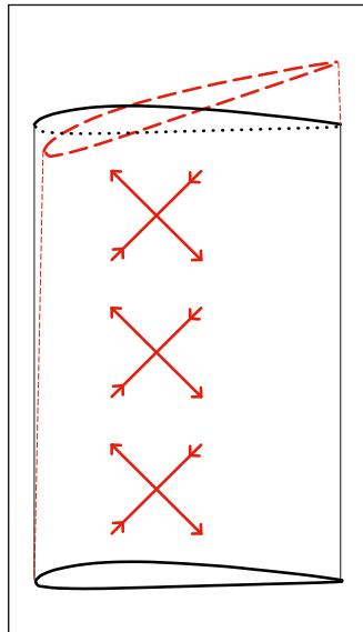
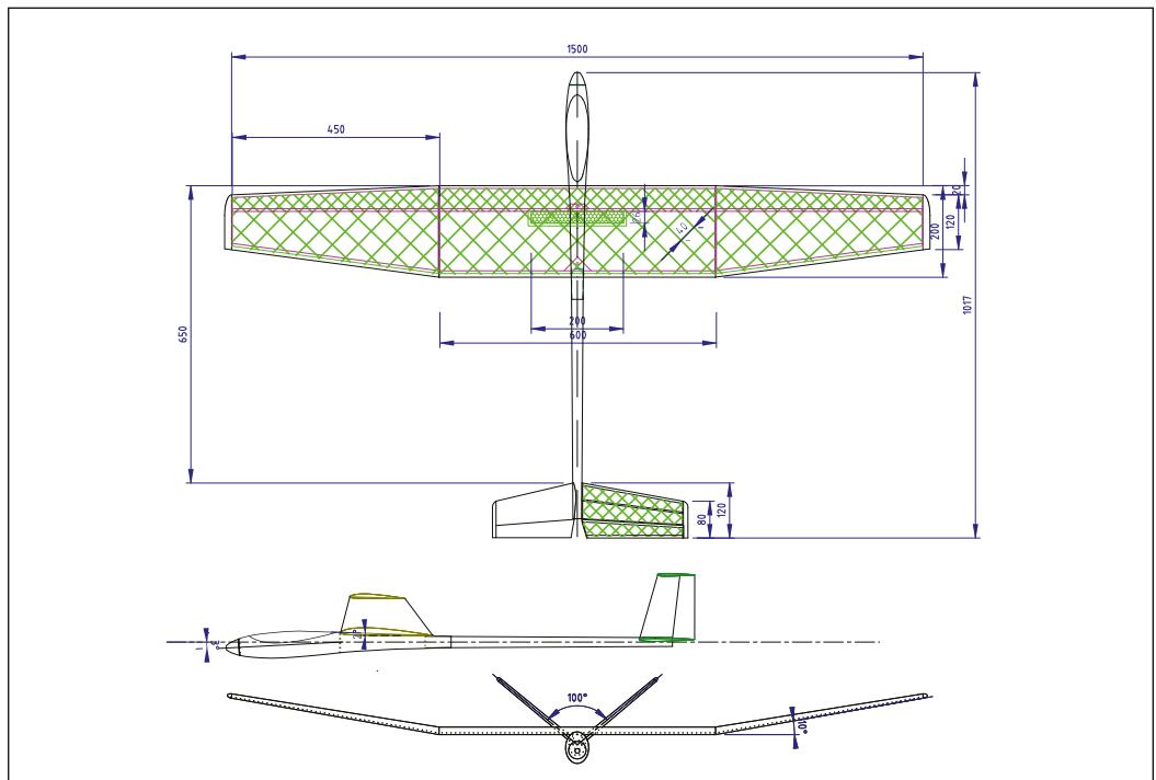
method. The ribs thus form a right-angled grid arranged at a 45° angle to the spar, because torsional forces generate tensile and compressive stresses against the wing skin, which run at a 45° angle to the wing centerline (Figure 1). This is clearly visible when a torsionally flexible, fabric-covered wing is twisted against the resulting fuselages in the fabric covering. An overview sketch (Figure 2) shows how I envisioned the model.
Actually, the geodesic rib construction method would be ideal for the increasingly common CNC manufacturing of individual parts. Unfortunately, however, this method was not available to me, so the wings and tail were built using traditional methods, which are described below.
First, create a rib grid that is large enough to allow you to cut out the grid pieces for the individual wings
and tail section parts; it’s best to make a sketch beforehand! To do this, cut a sufficient number of rectangular balsa strips, each slightly wider than the profile thickness and long enough to assemble the sketched grid. For the wing, in the case described here, this meant 20 mm wide and 0.5 m long. Lightweight 1.5-mm balsa was used. These strips were placed precisely on top of one another and clamped into a “comb” made, for example, from pine strips. This “comb” serves as a sawing template for the cuts in the rib strips. The spacing of the cuts corresponds to the grid width of the grid to be constructed; in my case: 40 mm behind and 20 mm in front of the spar. This is done to minimize the sagging of the fabric in the front third of the airfoil. On the rib block created in this way, the cuts can now be made up to the center of the
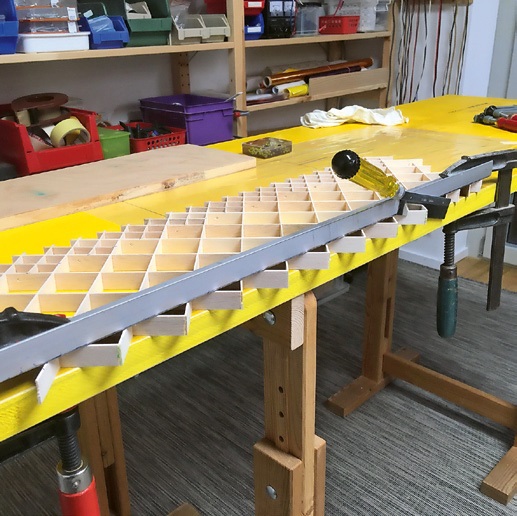
The slats should be cut using a miter saw with a depth stop (Figure 3).
The depth of the cuts is half the width of the strip, so the spacing is 20 or 40 mm, depending on the grid spacing. For strength reasons—since the profile is quite thin in that area—the tail section was constructed entirely with a 20-mm grid.
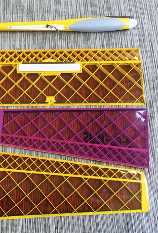
The balsa strips cut in this way can now be assembled into a lattice, and the intersections can be glued together using low-viscosity instant adhesive—preferably on the workboard with a sheet of PE film placed in between (Figure 4). Even after removing the lattice from the workboard, it exhibits a surprisingly high torsional strength.
Now you can saw out the lattice pieces needed for the individual wing segments and the tail section, taking care to make vertical cuts (preferably with a micro saw) (Figure 5).
Next, the airfoil end ribs made of birch plywood (which also serve as sanding templates for sanding the airfoil) are glued to the sides of the corresponding lattice piece (Figure 6).
Next, glue the balsa nose strip (cut or planed to a taper, but not yet sanded) and the trailing edge (CFRP profile, 6×0.8 mm with 8×1 mm balsa glued on, grain perpendicular to the CFRP strip) must be glued in place. For the end strip, a 1-mm step must first be sanded into the bottom of the grid.
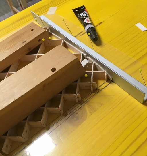
Using a long sanding block—slightly longer than the longest segment to be sanded (an aluminum angle profile with sandpaper taped to it works well for this)—you can now sand the wing profile along the segment end ribs (Figure 7). These should be marked with a felt-tip pen along the cut edges so that it is immediately visible when the sanding block touches a rib template and the grid has been sanded down to the profile shape. Of course, the templates must not be sanded down. The sanding block should only be moved sideways in the direction of the wingspan, and in the area of the leading and trailing edges, as parallel to them as possible.
The amount of sanding required can be kept to a minimum if lightweight balsa wood is used and if some of the excess rib wood is first removed (carefully!) with an orbital sander. Anyone who, like me, has trouble tolerating balsa dust should work with a dust extraction system and also wear a dust mask
; FFP2 masks have proven very effective for this!
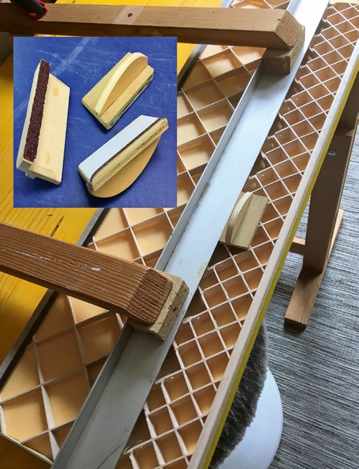
Next, sand in the recesses for the spar straps. A spar is mandatory, since the geodesic lattice is “responsible” only for the wing’s torsional stiffness, but not for its flexural stiffness. The best way to sand these out is with a simple sanding tool that matches the width and thickness of the spar strips, is easy to grip, and can be guided along an aluminum rail clamped at the appropriate profile depth (a sanding strip works well for this) (Figure 8).
Of course, there are still further steps required to complete the wing and tail assembly, but these will not be discussed in detail in this article, as they are not specific to geodesic construction. These include the installation of the lower spars, the spar web (consisting of individual pieces of balsa wood, with the grain running vertically and beveled at a 45° angle on the sides to match the rib line), and the insertion tubes (aluminum, with load-bearing
The construction of the fuselage from fiberglass/carbon fiber is not the subject of this article, so I will not go into detail here.
To wrap up this report, however, I’d still like to share a few details about the finished model. The ready-to-fly wing weighs 166 g, including the 8-g servo. That was roughly equivalent to
It was in line with my estimates during the planning phase and was therefore acceptable, especially since it felt quite sturdy to handle. The tail unit weighs 30 g; it could certainly be made lighter using a slat construction, but that would be an aesthetic break from the design. The entire ready-to-fly model weighs 460 g, resulting in a wing loading of 17 g/dm². Of course, today’s DLG gliders made of carbon fiber are significantly lighter. However,
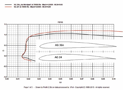
those are in a different league, and I was very satisfied with these values, as I had fully achieved the goals I had set for myself at the outset. The flight tests also showed that I could achieve what I considered the optimal center of gravity (54 mm, corresponding to a stability index of 16%¹) simply by adjusting the battery position. For the airfoil, I chose the AG 36n by Mark Drela, which has the structural advantage that the underside runs largely straight. Unfortunately, this convenience doesn’t come entirely free of charge. That is, the achievable maximum
The lift coefficient is slightly lower than that of similar profiles with a slightly greater curvature, as shown by a comparison with the AG 24—which is nearly the same thickness—at a Re number realistic for this model (Figure 10)2.
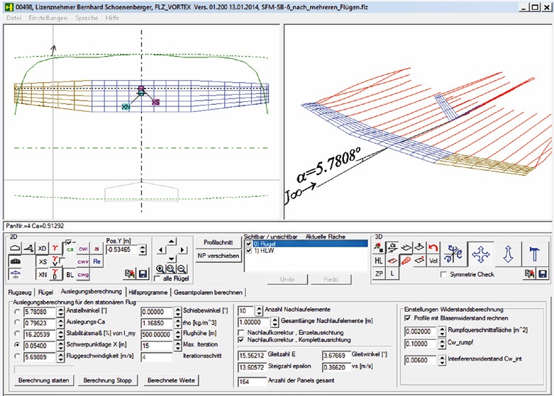
An FLZ vortex calculation using the specified center of gravity and the built EWD of 2.5° yielded the result shown in Figure 11.
The powertrain consists of an outrunner motor with 980 rpm*V and a diameter of 28 mm, an Aeronaut CamCar—
A bonZ 9x5' propeller, a 3S 500 mAh Li-Po battery, and a lightweight speed controller with BEC.
The first flights were uneventful, requiring hardly any trim adjustments. The model handles pleasantly and exhibits good circling behavior when making tight turns in thermals. The often-observed tendency to “fall into” the circle is barely noticeable here. Of course, a model like this flies much more comfortably in light winds than in turbulent air. In calm, thermal-free conditions, flight times of up to 30 minutes are possible.
The Excel data from two test flights, each consisting of seven climb and glide phases (Figure 12), conducted in calm conditions and thermal-free air on an early spring morning,
and measured using a variometer and altimeter, yielded the following average values: climb rate 7.4 m/s, sink rate 0.49 m/s. The FLZ vortex calculation resulted in a minimum sink rate of 0.37
m/s. Considering that I couldn’t always fly in a straight line, the measured values are quite plausible.
Overall, I can say that the design has
expectations (and hopes) and I am very satisfied with it.
1) According to FLZ-Vortex, www.flz-vortex.de by Frank Ranis
2) Based on Profili by Stefano Duranti


What's New at Leomotion.com

PRIDE AND GOOD IDEAS
 Markus Nussbaumer

News from HEBU

TEAM MANAGER "THIS" BOSSHARD
 Rodito Nussbaumer

ATOM, THE NEW DOUBLE-DECKER FROM CPLR
 Matthias Bosshard

INSIGHTS INTO THE HISTORY OF SEAPLANES

34th HAHNENMOOS ALPINE MODEL AIRPLANE CAMP
Res Dauwalder
CORSAIR F4U – A WARBIRD WITH A MEMORABLE LOOK
Jürgen Rosenberger, Jürgen Prinz
SUMMER FUN 2026 AT MG USTER
Martin Wunderli
F3A EUROPEAN CHAMPIONSHIPS IN ST-MACAIRE, FRANCE
Matthias Bosshard
52. 2026 ALPS CUP
 Emil Giezendanner

HORIZON HOBBY/LEMACO NEWS: MICRO OV-10 BRONCO 645 MM BY E-FLITE

TWIN TOWN PARTNERSHIP
Wolfgang Voeller
EURO CONTEST GLIDER ACRO TOUR AUSTRIA 2026

BY YOUTH, FOR YOUTH
Lorena Betschen
YOU KNOW WHAT I MEAN? 125 YEARS OF THE SWISS AERO CLUB
Emil Giezendanner
SMALL, MODEL-LIKE SAILBOATS
Res Dauwalder
TRY-OUT DAY AT MFV WETTINGEN
Urs Keller
WELCOME, NEW MEMBER!
Andrea Bolliger
FREE FLIGHT IN THE MIDDLE OF SUMMER
Urs Muntwyler
THE PC-21 STORY
Emil Giezendanner
COUPE DES ALPES – OBSERVE AND LEARN
Rodito Nussbaumer
NEWS FROM HEBU
 Julia Bucher

FROM 0 TO 100
Markus Nussbaumer
NOS REGION – A HUB FOR ELECTRIC AVIATION
Emil Giezendanner
MEMORIES
Wolfgang Völler
Have you almost forgotten about aircraft that take off and land vertically?
Emil Giezendanner
70 YEARS OF THE NIDWALDEN MODEL AIRPLANE CLUB
Martin Barmettler