
A Matter of Attitude
Apparently, there are some people who manage to turn a top-of-the-line ARF model into a “flying prosthetic.” And that’s due entirely to improper settings. Because: You fly the way you set it up! “Flying in and trimming”—this by no means refers to simply flying the model and adjusting the trims on the transmitter. That would be far too simple; there’s much more to these terms than that.
It all starts back in the workshop. Because if the angles on the model aren’t right in relation to each other, it won’t fly straight. And even the most advanced computer-controlled remote-control technology can’t fully compensate for tail surfaces that hang crooked on the fuselage. Adjusting the mixers, which is necessary in such cases, isn’t the ultimate solution either, because all settings are speed-dependent. And more than a few cases of a completely off-center center of gravity—because the model wasn’t properly balanced in the workshop—have resulted in a fatal somersault on the very first flight.
On the other hand, a neatly built and correctly calibrated model straight out of the workshop has a positive track record. Finding the control surface deflections that are ultimately necessary—since they must be adjusted to suit personal
control habits—as well as determining the optimal center of gravity position and EWD, actually fall under the category of flight testing and trimming.
An electric glider also falls into this category, although it involves two additional adjustment parameters: motor camber and side pull. The latter is negligible here—unlike in motorized models—but the camber is not. That said, we’ve now reached a point where even perfectionists will shy away from the effort required to shim the engine mount (on a frame where the engine has already been embedded in resin) and will opt for a mixer instead; when the engine is running, the elevator tends to drop slightly. With the right mixture, such an issue can be easily compensated for.
Things get really tricky when you have to set up a technical dinosaur equipped with a 6-flap wing (which, on top of that, also has spoilers), retractable landing gear with wheel brakes, a tow hook, and possibly a retractable engine. At least when every function must have its own channel.
But over the past decade, the industry has given us truly powerful tools in the form of perfectly finished models—specifically those from the crustacean faction—and remote controls using 2.4-gigahertz technology! Back in the megahertz days, 12 channels was the limit, so it wasn’t uncommon to run out of channels. Today, transmitters that can individually control 16, 18, or even more servos are a true blessing, especially for our large glider enthusiasts who rely heavily on servos.
But back to the beginning, because even a conventional four-flap wing needs to be properly adjusted. And that’s where a good, comprehensive data sheet—which should actually come with every model and list the corresponding basic settings—is a huge help. If, as has unfortunately often been the case lately, no setup data sheet is included, you can only rely on experience with similar models. With these default settings, you’ll need to fly the model step by step to fine-tune it.
The other, worst-case scenario probably looks like this: the EWD and center of gravity are off, and the ailerons aren’t
set up properly or aren’t differentiated at all. Pilots of such aircraft have long since fallen out of my category of those deserving sympathy, because anyone who, despite the best advice, refuses to see reason will likely spend their entire life flying a clunker through the air.
But these people don’t realize this, simply because they’ve never flown a properly set-up model. Another indication of the uncertainty among some less-experienced modelers regarding flight physics is the frequently heard opinion that a top-heavy model must follow an infinitely long, straight, banked flight path until it stalls, because the weight at the front of the fuselage supposedly pulls the thing downward. But popular belief on this matter is mistaken, as we’ll see.
But let’s not gloss over the fact that there are situations where the expectation of catching the culprit red-handed rarely comes to pass. Because if absolutely nothing about the model is right, things get particularly difficult. In that case, a detective-like approach is necessary, and the basic rule is: Always change only one parameter at a time, never two at once; otherwise, you won’t know afterward which change made a difference. →
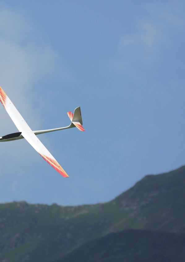
This is precisely why the mechanical conditions must be correct. This means not only that the wings and tailplane must be parallel to each other, but also that the servo output levers must be centered (with the exception of the aileron servos) and that the respective control surfaces must be centered as well. Minimal deviations—because half a turn on an M2 clevis can be too little or already too much—are permissible and often unavoidable. The author is satisfied if this electronic drift from the servo’s zero position remains below eight percent.
Anyone who takes this advice to heart will arrive at the airfield with a model that’s already reasonably preset and will not belong to that questionable group that first tries to electronically correct “skewed settings” on the model by frantically fiddling with the transmitter.
It is just as important that, in the workshop, the (hopefully) specified center of gravity be measured, the aileron deflections—including differentiation—be set, and, as a precaution for electric gliders, a mixer motor be assigned to the elevator and activated at a few percent. How much is needed must be determined through flight testing. To this day, the author has yet to come across any reasonable information regarding this—and the no less important issue of elevator mix—in the Butterfly manual.
But that’s not all by a long shot, because our glider needs
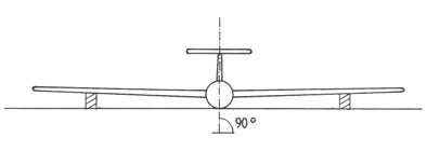
a so-called angle-of-attack difference, hereinafter referred to as EWD. The term “angle of attack” indicates that an angle is set here. The “difference,” on the other hand, refers to a discrepancy between the two. Since we generally fly with a positive EWD, the simplest way to explain this is as follows: The chord line of the horizontal stabilizer lies parallel to the imaginary fuselage zero line, whereas that of the wing is set at a positive angle. Figure 1 illustrates what is meant.
Now, don’t go thinking that the infamous half millimeter (on the wing surface!) is the deciding factor here. A practical example: Let’s assume a root depth of 25 cm on the wing surface. The model is propped up on the workbench; the fuselage is
visually in flight attitude, and the horizontal stabilizer is calibrated to zero relative to the workbench. Its leading and trailing edge distances from the work surface are therefore equal. The wing is set at a difference of 2.18 millimeters (the trailing edge is 2.18 mm closer to the workbench), which would correspond to an EWD of 0.5 degrees. So let’s quickly forget about those 2.18 mm and round it up to 2.2. If our model required a 1-degree EWD, however, that would already be 4.4 mm. To clarify: The difference in distance between the leading edge and trailing edge of the wing and the base would then be 4.4 mm! But since that’s barely measurable, we’ll round it up to 4.5 millimeters (Figure 2).
If the tailplane support—or, in the case of a pendulum-type cruciform tail, its mounting
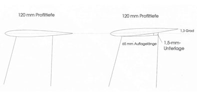
—is incorrect, the situation looks similar. Here, too, an example will clarify the issue: Our horizontal stabilizer has a root depth of 120 mm, but its contact length is only 65 mm—that is the critical dimension! If, for example, we place a 1.5-mm shim at the rear, this corresponds to a change in the EWD of 1.3 degrees! Figure 3 illustrates the situation. During alignment, the fuselage is always in flight attitude; the distance from the leading and trailing edges to the support surface is determined by the airfoil shape. For current-generation models, we can assume that these specifications are correct. We’ll find out later what to do if that’s not the case. But our wing also has an airfoil, our model has an overall design, and this interplay is what makes
it what it is: strong in thermals, good for cross-country flying, or simply an all-rounder. That said, in the case of the latter—provided it doesn’t have flaps—there are often slight compromises in both directions, though this doesn’t prevent it from being the most versatile aircraft.
Let’s take one from Helmut Quabeck’s popular series, the HQ 3/12. The numerical code tells us that this is a profile with a 3% centerline camber and a 12% thickness (Figure 4). A profile with this camber and thickness inherently excels at thermal flying. The decision to prioritize thermal performance was therefore made from the very beginning when selecting this airfoil. That doesn’t mean, however, that a model equipped with an HQ 3/12 or a similar airfoil would be a slowpoke. Colleagues who fly primarily in flat terrain will opt for an EWD of about two degrees here, though this makes fast flying virtually impossible, since the model—if it is to go fast (which it isn’t really capable of with this configuration anyway)— must be kept in a steep bank at all times using elevator input.
An example that points exactly in the opposite direction would be the use of an RG 14. No sensible designer would specify this airfoil for a model intended primarily for thermal flying. For an all-around model intended for use on slopes as well, however, it would be a good choice in combination with a significantly lower EWD, approximately one degree.
As a counterpart to the HQ 3/12 mentioned earlier, let’s consider an HQ 1.5/12 (Figure 5). Here, too, the thickness is 12 percent, but its centerline camber is only 1.5 percent. If we compare the two drawings,
it quickly becomes clear what is meant (Figures 4 and 5). This profile, which comes close to having all-around qualities, will never perform as well in thermals as its more strongly cambered counterpart. This example assumes wings without camber flaps.
Before heading to the airfield, the center of gravity must be weighed according to the spec sheet; our model is also balanced around the longitudinal axis, with both wing halves having the same static weight. In most cases, this will mean that
some trim lead will be needed in one of the wing tips.
This isn’t going to be some highly scientific treatise—because the “negative turn roll moment” that’s so often bandied about among model airplane enthusiasts doesn’t actually exist—but rather practical knowledge that even Manfred Metzger and Berthold Becker will understand. Consequently, what is said here should be viewed as generally correct.
The much-cited and much-maligned hand launch doesn’t happen here either. It’s far too dangerous on flat ground. There’s far too little lift under the wings! The safest way to get a glider airborne is the F-tow. With electric gliders, the motor’s power puts us in a self-sufficient position. Hand launching without a motor—including, or perhaps especially, with gliders—is permitted only on a steeply sloping hillside.
Once the model is in the air, the first priority is to get it into a reasonable level—
to move it straight ahead to the right. This will likely require some trim adjustments during the first flight—the fewer, the better. To do this, we’ll actually use the trim controls on our transmitter. As far as the EWD is concerned, pilots of models with a pendulum tail have a slight advantage, since this type of tail does not have a fixed damping surface. But even with a damped tail, it doesn’t matter at first whether the rudder flap is slightly off-center for level flight. The EWD is completely unaffected by whether it’s adjusted by shimming the tailplane damping surface at the relevant point (i.e., at the rear or front) or by trimming the rudder. The additional drag caused by a trimmed rudder is also negligible at first.
So: First, determine the center of gravity (this has already been done in the workshop), and then trim the EWD with the elevator in flight so that our model flies straight—
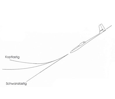
and this brings us to the most serious of all errors in reasoning: whether the model is nose-heavy or tail-heavy. To check these parameters, we need to pitch our test model, bring it into a banked flight—about 30 degrees is sufficient—and then suddenly release the elevator stick.
What happens next is crucial for how we proceed. If the model maintains its current path for a while and then levels off on its own in a gentle arc, we can forget all about the rest of the trimming around the transverse axis—an absolute stroke of luck! If, on the other hand, it pitches up more or less abruptly after releasing the control stick, this indicates nose-heavy behavior. If the pitch angle—
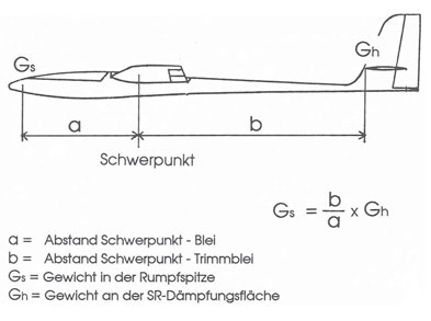
If the aircraft maintains its flight path or even becomes steeper, it is tail-heavy.
At first glance, this statement seems counterintuitive, but it isn’t. If we visualize the conditions on the model, we’ll quickly understand why. What actually happens when we force a horizontal straight-ahead flight by adjusting the trims on the transmitter? In the case of nose-heavy flight—which isn’t so bad for the first few flights—we have to move the trim up to achieve this flight path. If we now bank the model—about 30 degrees is enough—its speed increases. If we now suddenly release the stick, our up trim takes effect more strongly; the model will inevitably pitch up, since the up-trimmed aileron—depending on the speed—doesn’t allow for anything else.
In the opposite case—that is, if the center of gravity is too far aft—down trim is necessary so that our plane flies reasonably level and straight ahead. If we repeat the pitching maneuver, the opposite conditions occur (Figure 6).
Regarding the specified EWD: If the wing’s angle of attack relative to the fuselage’s longitudinal axis is too small, the fuselage will “hang down.” We’ve exaggerated this in Figure 7. In (1), the wing is set at an excessively high angle relative to the longitudinal axis. With this setting, the model will follow the flight path shown in (2) for a reasonable straight-ahead flight—a visually impossible scenario, since the fuselage is constantly suspended in the air in a dive. The corrected version is shown in (3). The excessive angle of attack at the airfoil leading edge has been corrected, resulting in a reasonable flight attitude.
Normally, it will probably never be this extreme, because then
The designer would have made a huge mistake. Furthermore, it’s simply not possible to level out a wing that’s set at too steep an angle—at least not if the fuselage has a profiled shape. If we have a fuselage like this, where the profile alignment is so far off
the longitudinal axis, all is lost. The only way to fix this would be with a great deal of effort, putty, and sanding around the profile junction—which would also require a corresponding touch-up paint job. Figure 8 shows an airfoil with a chord line that defines our measurement points.
The other case isn’t ideal either, but it’s significantly better. Our horizontal stabilizer mounting isn’t correct. This assumes a damped T-tail or cruciform tail. In flight, we’ll initially have to rely on the trim on the transmitter again. Because the EWD doesn’t care at all… but we’ve already covered that. By gradually
adding shims, we now work our way toward the EWD that brings the rudder flap to the neutral position and gives the model reasonable flight characteristics.
Please proceed in small steps, because as we learned earlier, 1.5 mm on a horizontal stabilizer with a root depth of 120 mm is—
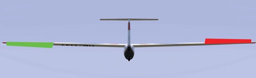
We fly the way we set up our planes—that’s a fact. After all, even a top pilot won’t fly any better with a poorly set-up plane than a “good Sunday pilot” with a perfectly tuned model. This includes the correct aileron deflections as well as proper aileron differentiation (Figure 9). For models with flaps—which are generally braked using the butterfly control—the differentiation reduction function must also be set to 100 percent. What does this function do? Well, due to the set differentiation, the aileron moving downward travels a significantly shorter distance than the one moving upward. With butterfly brakes, this causes the affected aileron to move too little in response to a control input, resulting in the desired flight attitude correction occurring much too slowly. The set 100 percent reduction
that, with the flaps fully extended, differentiation is completely disabled in this flight condition, resulting in full maneuverability.
For models that react very directly and sharply to control inputs, it has proven effective to set appropriate Expo values. For the elevator, please do not exceed 15 percent; otherwise, the control feel becomes too “sluggish.” With our rudder actuators equipped with turntables or servo levers, this approximately 15 percent corresponds to nothing more than a (desired) linearization.
To get the model to fly a clean circle and prevent annoying yawing around the vertical axis (which experts call negative aileron yaw moment), it is essential to set aileron differential. The amount depends on the size and shape of the control surfaces. I’ve never had a glider that didn’t require at least 30 percent. If this setting isn’t used, our glider will drift out of the turn—and preferably at the very moment when we absolutely can’t afford it: during slow flight, when
we’re struggling to stay airborne, or when stalling on a slope. Of course, the same applies in level flight. So, as a general rule: Models that are properly tuned are the better gliders!
Let’s use an example to illustrate how important it is to have a properly adjusted aileron differential. The differential for normal flight and circling is set and works correctly. However, when performing a roll, it can be observed that the glider does not roll cleanly along the longitudinal axis but rather “wobbles”—in such a way that, when approached from the right and rolled clockwise, it shifts toward us. This simply means that the right aileron moves up too far relative to the other. In other words, the aileron moving downward isn’t traveling far enough. So, by reducing the differential, we need more travel. All of this falls under the category of fine-tuning, but that is exactly what is needed, because all our efforts stem from the desire to create a model that flies as perfectly as possible.
R.M.
Check the center of gravity by piercing the model. Fly at an angle of approximately 30 degrees, then suddenly release the elevator control stick. If the model pitches up, it is top-heavy. Ballast must be removed from the nose accordingly. If the flight path is maintained for some time and the model then automatically enters a gentle flare, the setup is correct. If the model does not flare or flares too slowly, or if it tends to take an even steeper flight path, it is tail-heavy. Add ballast to the nose.
The glider must be able to perform a clean turn. This also applies to rapid changes in bank angle; under no circumstances should it yaw around the vertical axis when the ailerons are moved. Full deflections must be applied during this test. The differentiation must be increased gradually until comfortable flight behavior is achieved; it is not a fault if the model still rolls cleanly through a roll at this point. If this is not the case, the differentiation must be adjusted differently for aerobatics using an external switch during this phase of flight.
Both spoilers must extend and retract by the same amount at the same time; otherwise, the model will veer off its intended flight path. Depending on the effect of the spoilers, you can gain a little altitude during the landing phase. If the spoilers aren't effective enough, you can add a little butterfly control.
All ailerons must have the same deflection values; otherwise, our model will pull to one side, which is undesirable! Adjust the depth accordingly. Set the aileron differentiation reduction to 100 percent.
Ralph Müller


News from HEBU

PRIDE AND GOOD IDEAS
 Markus Nussbaumer

TEAM MANAGER "THIS" BOSSHARD
 Rodito Nussbaumer

YOU KNOW WHAT I MEAN? 125 YEARS OF THE SWISS AERO CLUB
 Emil Giezendanner

F3A EUROPEAN CHAMPIONSHIPS IN ST-MACAIRE, FRANCE
 Matthias Bosshard

HORIZON HOBBY/LEMACO NEWS: MICRO OV-10 BRONCO 645 MM BY E-FLITE

ATOM, THE NEW DOUBLE-DECKER FROM CPLR
Matthias Bosshard
SUMMER FUN 2026 AT MG USTER
Martin Wunderli
52. 2026 ALPS CUP
Emil Giezendanner
TWIN TOWN PARTNERSHIP
Wolfgang Voeller
CORSAIR F4U – A WARBIRD WITH A MEMORABLE LOOK
Jürgen Rosenberger, Jürgen Prinz
SMALL, MODEL-LIKE SAILBOATS
Res Dauwalder
TRY-OUT DAY AT MFV WETTINGEN
Urs Keller
WELCOME, NEW MEMBER!
Andrea Bolliger
What's New at Leomotion.com

COUPE DES ALPES – OBSERVE AND LEARN
Rodito Nussbaumer
EURO CONTEST GLIDER ACRO TOUR AUSTRIA 2026

BY YOUTH, FOR YOUTH
Lorena Betschen
INSIGHTS INTO THE HISTORY OF SEAPLANES

34th HAHNENMOOS ALPINE MODEL AIRPLANE CAMP
Res Dauwalder
FREE FLIGHT IN THE MIDDLE OF SUMMER
Urs Muntwyler
THE PC-21 STORY
Emil Giezendanner
NEWS FROM HEBU
 Julia Bucher

FROM 0 TO 100
Markus Nussbaumer
MEMORIES
Wolfgang Völler
NOS REGION – A HUB FOR ELECTRIC AVIATION
Emil Giezendanner
DO YOU KNOW WHAT I MEAN IN THE LAND OF SMILES?
Emil Giezendanner
Have you almost forgotten about aircraft that take off and land vertically?
Emil Giezendanner