
JTA Innovations Slick
In model aviation, Jase Dussia is the pilot who revolutionized 3D flying. Using various models from Extreme Flight, he consistently performs spectacular flights. However, this model cannot be flown in the backyard or in a hangar. He founded his own company, JTA Innovation, to sell his indoor models. There is now a wide selection of different models and designs, all of which have a very similar construction. The models are made of 8 mm EPP, which is printed with cool designs and reinforced with carbon fiber.
The following accessories are required/recommended for building an indoor EPP model:
- Medium-viscosity superglue – activator
- UHU-Por
- Sharp knife
- Possibly a soldering iron
- Screwdriver – Lighter
- Baking paper
- Utility knife
The first step in building an EPP model is to bend the aileron hinges. For EPP models, the hinges are cut with a hot wire, which melts the EPP at these points. To ensure the control surfaces move as freely as possible and thus reduce the strain on the servos, all control surfaces should be folded down and weighted in this position for at least 2 hours (see Figure 1).
For building an EPP model, both superglue and UHU-Por are used. When, how, and where each adhesive (superglue and UHU-Por) is applied has a significant impact on the model’s properties. Many who have built a model with superglue before are surely familiar with the problem: the model sticks to the workbench. To remedy this, there’s a simple trick: parchment paper. Thanks to the parchment paper’s non-stick properties, the model can be rotated and turned without sticking to the table (see Figure 2).
The model is primarily assembled using superglue. However, since EPP is a soft and flexible material, this should be taken advantage of. This makes the model more crash-resistant. To ensure the model is stable against twisting but can also absorb impact, there’s a simple rule for gluing: use UHU-Por for foam, and superglue for foam reinforced with CFRP. Only the bottom and top views of the fuselage side view are glued to the top view using UHU-Por; the rest is glued with superglue (see red markings in Figure 3).
The landing gear is an important component of every aircraft, so it must be securely glued in place. You can either install the included landing gear parts or wrap them with Kevlar thread and secure them with superglue. This ensures that the landing gear is securely fixed in the fuselage (see Figure 4).
The Slick is known for its excellent flight characteristics. If you’re looking for a model to fly in your backyard, as a training model for new maneuvers, or simply as an all-around model for indoor and outdoor use, JTA’s models are the perfect choice. What makes this model special is that it flies just like a large 3D model. The control response is excellent; the limits are set by the radio control system, not the model itself. Whether it’s roll combinations, snaps rolls, time rolls, harrier maneuvers, torque maneuvers, all kinds of spins, or new maneuvers from the XA (Xtreme Acrobatics) repertoire—they’re all possible with the Slick. However, XA maneuvers that require mass are almost impossible to fly with slowflyers, since the airflow cannot stall quickly enough—or in some cases, not at all. With the Slick, it is possible to fly some of these XA maneuvers, as a stall can be induced in a manner similar to that of full-scale models. Compared to other products of this size, the Slick has better stability in the air and, due to its higher-
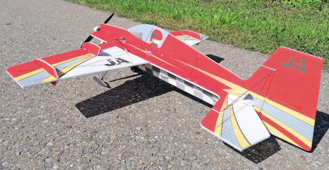
Due to its lighter weight, it is also significantly more susceptible to wind. Thanks to the 8-mm EPP, the model still flies very slowly and is therefore well-suited for indoor flying.
It is not designed for a 3S power source, so we recommend operating this model with a 2S battery.
The power set used is actually designed for 2S, but since suitable 3S batteries were already available, a slightly smaller propeller was used. Even with 2S, the motor has enough power to move the Slick through all maneuvers with plenty of power and no problems. With a 3S setup, the motor generates an enormous amount of power, resulting in far too much thrust for the model; at full power, the model turns into a rocket.
If high-voltage (HV) servos are used, the 2S power setup offers an additional advantage, as the servos can be powered directly from the flight battery. If the model is powered by a 3S setup, the battery voltage must be reduced from 11.1 V to 7.4 V. For this purpose, a homemade 7.4 V BEC was used in this model. Furthermore, the model’s weight with a 2S setup is approximately 5–20 g. The 2S power setup therefore offers many advantages over
the 3S power setup; therefore, it is recommended to operate this model with a 2S battery.
| Electronics | With slow flyers, every gram counts, so after just a few flights, all servo cables were replaced with enameled copper wire and soldered directly to the receiver. The significantly lighter enameled copper wires and the removal of the servo connectors saved about 10 g (approx. 5% weight reduction). But be careful: To make the components lighter, you’ll need a good soldering iron and expertise in soldering. Otherwise, components could be damaged. |
|---|---|
| Model | An optimization to the model that takes the approach of replacing the servo cables and connectors to the extreme would be to save another 15–30 g (approx. 10% weight reduction). This would require using a different type of carbon fiber, but this was not implemented on this model. This optimization would be very costly, as the included accessories (carbon fiber, linkage parts, landing gear, etc.) would not be used! In this case, all carbon rods would be replaced with tubes, the flat profiles with smaller flat profiles, the square profiles (landing gear) with tubes, and the square profile in the wing would be omitted. In addition, the wheels would be omitted from the landing gear, and the linkages would be replaced with lightweight fiberglass-reinforced plastic (FRP) linkages. |
| Linkage | To fly a model as precisely as possible, a play-free linkage system for the control surfaces is very important. The included linkage parts work very well. The linkages still have minimal play, which can be minimized with small plastic clevises. |
| Comment | Personally, I build all my slowflyers this way—this is probably a hangover from my F3P days. The Slick was flown during the first test flights without any optimizations (such as replacing cables). The difference in flight characteristics with the optimization (lightening the electronics load) is barely noticeable, so the model can easily be built without any optimizations. Whether such optimizations are worth it is up to each individual to decide. After all, the models fly very well “out of the box.” |
As an alternative to HV servos, standard micro servos (low voltage) can also be used. With these servos, the 5V BEC built into the ESC is used, and the servos can be connected to the receiver as usual without any additional components. Are expensive HV servos necessary for a model like this? No, a model like this can be flown just fine with standard micro servos. When comparing HV and LV servos, HV servos have more torque and are faster. Additionally, HV servos of this size are usually more expensive. However, the torque of LV servos is more than sufficient for flying such models. Therefore, both LV and HV servos can be used in this model.
| Parameters | Components Used | Alternatives |
|---|---|---|
| Motor | T-Motor AS2304-1800 | 20–24 g motor ; approx. 1800 kV for 2S; approx. 1500 kV for 3S |
| ESC | T-Motor 12 A | 10–15 A ESC |
| Propeller | Falcon 8.5x3.7 | 9x4 |
| Battery | Swaytronic 3S 650 mAh 35C | 2s 450–650 mAh |
| Ailerons | KST A08 | KST DS113MG |
| Elevator | KST X06 V5.0 | HS45HB/HS-40 |
| Rudder | KST X06 V5.0 | HS45HB/HS-40 |
| Receiver | Futaba R2106GF | Lightweight 4-channel receiver |
| Weight | 245 g RTF | - |
| Optimized weight | 230 g RTF | - |


TEAM MANAGER "THIS" BOSSHARD
 Rodito Nussbaumer

YOU KNOW WHAT I MEAN? 125 YEARS OF THE SWISS AERO CLUB
 Emil Giezendanner

F3A EUROPEAN CHAMPIONSHIPS IN ST-MACAIRE, FRANCE
 Matthias Bosshard

News from HEBU

SUMMER FUN 2026 AT MG USTER
Martin Wunderli
TRY-OUT DAY AT MFV WETTINGEN
Urs Keller
52. 2026 ALPS CUP
Emil Giezendanner
BY YOUTH, FOR YOUTH
Lorena Betschen
ATOM, THE NEW DOUBLE-DECKER FROM CPLR
Matthias Bosshard
CORSAIR F4U – A WARBIRD WITH A MEMORABLE LOOK
Jürgen Rosenberger, Jürgen Prinz
SMALL, MODEL-LIKE SAILBOATS
Res Dauwalder
What's New at Leomotion.com

TWIN TOWN PARTNERSHIP
Wolfgang Voeller
EURO CONTEST GLIDER ACRO TOUR AUSTRIA 2026

INSIGHTS INTO THE HISTORY OF SEAPLANES

34th HAHNENMOOS ALPINE MODEL AIRPLANE CAMP
Res Dauwalder
HORIZON HOBBY/LEMACO NEWS: MICRO OV-10 BRONCO 645 MM BY E-FLITE

COUPE DES ALPES – OBSERVE AND LEARN
Rodito Nussbaumer
PRIDE AND GOOD IDEAS
 Markus Nussbaumer

FREE FLIGHT IN THE MIDDLE OF SUMMER
Urs Muntwyler
THE PC-21 STORY
Emil Giezendanner
WELCOME, NEW MEMBER!
Andrea Bolliger
NEWS FROM HEBU
 Julia Bucher

FROM 0 TO 100
Markus Nussbaumer
MEMORIES
Wolfgang Völler
NOS REGION – A HUB FOR ELECTRIC AVIATION
Emil Giezendanner
Have you almost forgotten about aircraft that take off and land vertically?
Emil Giezendanner
70 YEARS OF THE NIDWALDEN MODEL AIRPLANE CLUB
Martin Barmettler