
RCS Design Course – Theory and Practical Application
In the following papers on the interpretation of RCS models, I have proceeded from the premise that it is hardly possible for every interested modeler to collect and evaluate the numerous articles scattered throughout various professional journals.
Individual theoretical treatises, selected at random from the vast body of material, are of little use to the average model builder, since the equally important or directly related peripheral topics are missing or inaccessible. The entire subject matter was covered in a design course conducted by Region 5 in November 1971, and it was from this group that the desire arose to publish this theoretical and practical treatise.
Heinrich Disler
1. Wing Geometry (Area, Aspect Ratio)
No. 6, December 1972
2. The Reynolds Number
No. 7, February 1973
3. The Polar Chart
No. 8, April 1973
4. The Airfoil
No. 9, June 1973
5. Model Design
No. 10, August 1973
6. Calculation Example
No. 11, October 1973
7. Calculation Example (Continued)
No. 12, December 1973
Calculation of Wingspan and Aspect Ratio for Non-Constant Geometric Wing Profiles.
In the following paper, I intend to present, in an easily understandable manner, a method for calculating the wingspan and aspect ratio of wings or tail surfaces, assuming a given area and internal profile depth.
As initial parameters for all calculations, we will use an RCS wing with an area of $50 \text{ dm}^2$ and an internal profile depth of $2.2 \text{ dm}$.
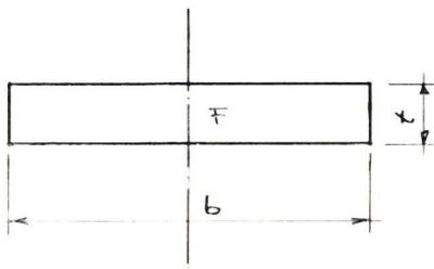
| F | = 50.0 dm2 |
| t | = 2.2 cm |
| b = F / t | = 50.0 / 2.20 = 22.73 dm |
| λ = b / t or b² / F | = 22.73 / 2.20 = 10.33 = 22.73² / 50.0² = 10.33 |
- F = Wing area in dm²
- b = Wingspan in dm
- ti = inner airfoil depth in dm
- ta = outer airfoil depth in dm
- tm = average airfoil depth
- λ = wing aspect ratio
For aerodynamic reasons, ta should not be less than 0.6 ti.
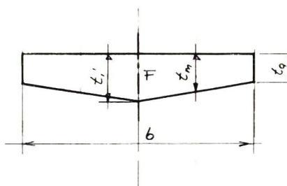
| F | = 50.0 dm² |
| 10 | = 2.2 dm |
| ta | = 0.6 ti = 0.6 × 2.2 = 1.32 dm |
| tm | = (ti + ta)/2 = (2.20 + 1.32)/2 = 1.76 dm |
| b | = F / tm = 50.0 / 1.76 = 28.41 dm |
| λ | = b / tm = 28.41 / 1.76 = 16.14 = b² / F = 28.41² / 50.0 = 16.14 |
This wing planform is probably the most commonly used in model aircraft.
In this case, we can no longer determine the wingspan b directly from tm.
First, we need to consider what the ratio between the inner (rectangular) wing and the outer (trapezoidal) wing should be.
Wind tunnel tests have shown that, relative to half the wingspan, the optimal ratios are:
bi = 2/3 b' and ba = 1/3 b'
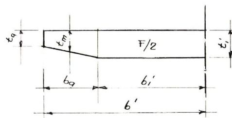
F/2 = ( ti' × 2/3 b' ) + (( ti' + 0.6 ti' ) / 2 ) × b'/3 | |
Example: | |
b1' = 2 × 6' / 3 = 8.09 dm' |


News from HEBU

TEAM MANAGER "THIS" BOSSHARD
 Rodito Nussbaumer

YOU KNOW WHAT I MEAN? 125 YEARS OF THE SWISS AERO CLUB
 Emil Giezendanner

F3A EUROPEAN CHAMPIONSHIPS IN ST-MACAIRE, FRANCE
 Matthias Bosshard

52. 2026 ALPS CUP
Emil Giezendanner
PRIDE AND GOOD IDEAS
 Markus Nussbaumer

ATOM, THE NEW DOUBLE-DECKER FROM CPLR
Matthias Bosshard
CORSAIR F4U – A WARBIRD WITH A MEMORABLE LOOK
Jürgen Rosenberger, Jürgen Prinz
SUMMER FUN 2026 AT MG USTER
Martin Wunderli
TRY-OUT DAY AT MFV WETTINGEN
Urs Keller
TWIN TOWN PARTNERSHIP
Wolfgang Voeller
BY YOUTH, FOR YOUTH
Lorena Betschen
SMALL, MODEL-LIKE SAILBOATS
Res Dauwalder
What's New at Leomotion.com

HORIZON HOBBY/LEMACO NEWS: MICRO OV-10 BRONCO 645 MM BY E-FLITE

COUPE DES ALPES – OBSERVE AND LEARN
Rodito Nussbaumer
EURO CONTEST GLIDER ACRO TOUR AUSTRIA 2026

INSIGHTS INTO THE HISTORY OF SEAPLANES

34th HAHNENMOOS ALPINE MODEL AIRPLANE CAMP
Res Dauwalder
WELCOME, NEW MEMBER!
Andrea Bolliger
FREE FLIGHT IN THE MIDDLE OF SUMMER
Urs Muntwyler
THE PC-21 STORY
Emil Giezendanner
NEWS FROM HEBU
 Julia Bucher

FROM 0 TO 100
Markus Nussbaumer
MEMORIES
Wolfgang Völler
NOS REGION – A HUB FOR ELECTRIC AVIATION
Emil Giezendanner
Have you almost forgotten about aircraft that take off and land vertically?
Emil Giezendanner
DO YOU KNOW WHAT I MEAN IN THE LAND OF SMILES?
Emil Giezendanner