
Everything You Should Have Known Long Ago About Your Model Aircraft's Avionics
In the propulsion system of a modern electric model aircraft, current is the most important factor of all that we need to understand and control in electric flight. The selection of components such as the propeller, motor, ESC, and battery influences the current and, when chosen wisely, is the source of impressive performance, long flight times, and thus flying enjoyment. However, if the current in the power system falls into an undesirable range—for example, outside a component’s specifications—due to an unfortunate choice of one of the components listed above, it can cause malfunctions, damaged components, and frustration at the airfield. Fortunately, current can be measured very accurately by following a few rules, making it something anyone can master. In this workshop, we’ll cover these rules as well as the pitfalls to avoid.
$$U = R \cdot I$$
Fig. 1: Ohm’s Law.
As in the previous article, we’ll need a digital multimeter (DMM) this time as well. As we showed in Issue 1/09, most DMMs alone are unfortunately not suitable for measuring currents > 10 A. To measure the much higher currents in the drive, we therefore need an additional component: the shunt.
A shunt is the term for a precise, low-resistance resistor (often in the m$\Omega$ range—
(rich). This allows us to easily measure currents up to 100 A or more, always in conjunction with a simple DMM. The basic principle used when working with a shunt to determine the current is Ohm’s law (Figure 1). This describes the relationship between current, voltage, and resistance. If Ohm’s law is written slightly differently, as shown in Figure 2, we obtain an expression directly for the current I. Specifically, this means that by measuring the voltage U across a
$$I = \frac{U}{R}$$
Fig. 2: Ohm’s Law, rearranged in terms of current I.
Given the known resistance R, the unknown current I flowing through it can be calculated. In other words: Let the current from the drive system flow through our shunt, and use the DMM to measure the voltage across the
| Input | ||
| Desired resistance R [m$\Omega$]: | 1 | |
| Required conductor cross-sectional area A [mm²]: | 1.5 | Enter the desired resistance of the shunt. Enter the desired conductor cross-sectional area here. |
| Result | ||
| Required copper wire length L @ 20°C [cm]: | 8.4 | Cut the copper wire to this length. |
| Power loss @ 25A [W]: | 0.6 | Take the power loss into account. The shunt will heat up accordingly! |
| Power dissipation @ 50A [W]: | 2.5 | |
| Power dissipation @ 100A [W]: | 10.0 |
Tips and Tricks:
Never coil the shunt or bunch it up in any way. The shunt must always be laid out as a straight conductor.
Avoid lengths greater than 10 cm. If the calculated wire length is too long, choose a smaller cross-sectional area or reduce the desired resistance value.
Caution is advised for power dissipation greater than 3W. The shunt will heat up quickly.
Your Shunt:
Fig. 3: Our shunt calculator. It quickly and easily calculates the necessary parameters for building your own shunt.
Shunt—this way, we can then determine how much current has flowed through this shunt. Voilà—and now we know the current in our drive system.
Of course, you can make one yourself. We build ours using electrical wire. At www.blog.innoflyer.ch, you can download a “shunt calculator” that helps you design a shunt to your liking without needing much technical knowledge (Figure 3). We use
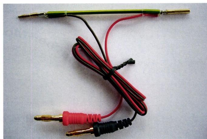
use copper electrical wire with a cross-sectional area of 1.5 mm². This type of wire is available at any hardware store. Our shunt should ultimately have a resistance of 1 m$\Omega$. This resistance depends on the length of the wire and the cross-sectional area used. Using our shunt calculator, we determined a length of 8.4 cm. Cut the wiring to this length and equip it, as shown in Figure 4, with your connector system (the one used on the battery and controller) and the voltage measurement lead (we used a charging cable). Now we’re ready to measure the current. For those who aren’t quite as adept with a soldering iron, our Innoflyer current measurement adapter A1-PWR60 offers an affordable DIY alternative.
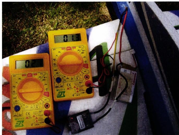
Figure 5 shows a typical measurement setup using the homemade shunt. The shunt is simply connected in series between the battery and the controller (so that the current from the drive system flows through it
). The voltage across the shunt is then measured with the DMM in the 200-mV DC range during operation. The voltage reading in mV displayed on the DMM corresponds directly to the actual current in A (this applies only if a 1-m $\Omega$ shunt and a DMM in the mV range are used). Our homemade shunt, despite its simplicity, has its limitations. For example, its resistance value is highly temperature-dependent. If its temperature increases by 50°C, the resistance changes by just under 20%. The current measurement is consequently inaccurate by this percentage. Therefore: Always measure only briefly so that the shunt does not heat up much above room temperature. Our Innoflyer current measurement adapter A1-PWR60 does not have these issues. It is highly accurate over a wide temperature range. As an alternative to the shunt, clamp-on ammeters are also available from specialty retailers. However, these are significantly more expensive than the solution described here and do not provide more accurate measurement results.
The method of current measurement
is only correct and meaningful when dealing with direct current. With our modern switched-mode motor controllers, however, this applies to only one operating point: full load. Here, the controller is operating at nearly 100% duty cycle, and the current flowing from the battery into the controller is virtually direct current. The results obtained with the shunt (or clamp-on ammeter) are correspondingly accurate and meaningful. However, in the partial-load range, this is no longer the case. The exact waveform of the current depends on the motor used (inductance) as well as on the controller itself (switching frequency, input capacitances, switching patterns). The more the current being measured deviates from direct current, the greater the measurement error when using the method discussed above. This is not just a matter of a few percent; errors of up to 100% must be expected. Furthermore, we will always measure too little current; that is, if the actual current is 30 A, with a measurement error of 100% we will measure only 15 A! Such a result is useless. To avoid this, we must, in the partial-load range—as already mentioned in the previous—
In this workshop, we will measure the root mean square (RMS) value. You can find more information about the root mean square value and its definition on our blog at www.blog.innoflyer.ch. By following the precautions below, we can ensure accurate measurements even in the partial-load range (and, of course, at full load as well).
Get a DMM with a “Voltage RMS” range selection—often somewhat misleadingly labeled “TrueRMS.” The requirements for this RMS measurement function are quite high, so it must be a very good—and therefore quite expensive—professional-grade meter. When making a purchase, you must find the following specifications listed in the device’s manual (otherwise, steer clear): a frequency range from DC to 250 kHz and a crest factor of 4 or higher. Incidentally, these requirements also apply to a clamp meter intended for measuring currents in the partial-load range. Equipped with such a high-quality device, you can then confidently measure currents from partial to full load using the shunt measurement method described above. A very cost-effective option is our Innoflyer—
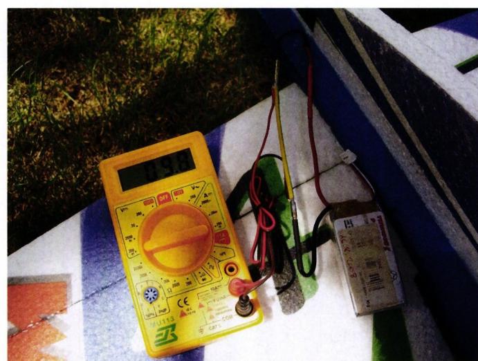
Current Measurement Adapter A1-PWR2RMS. This is a shunt that—when equipped with the appropriate additional electronics—is capable of performing accurate RMS measurements using an inexpensive DMM. Figure 6 shows the measurement setup with this current measurement adapter and a simple DMM in the partial-load range. For direct comparison, an identical DMM has also been connected in parallel with our homemade shunt in the circuit. The two results show a remarkably large difference! So, in the future, make sure to distinguish whether you are measuring at full or partial load and select the appropriate measurement mode accordingly.
With these basics, you are now able to perform current measurements easily, quickly, and, above all, accurately. This allows you to conduct interesting experiments, such as when tuning the propeller. Share the insights you’ve gained with your colleagues and continue to optimize your models.
All the materials you need to replicate this workshop at home in your workshop are available at a well-stocked model shop or at www.innoflyer.ch.


TEAM MANAGER "THIS" BOSSHARD
 Rodito Nussbaumer

52. 2026 ALPS CUP
 Emil Giezendanner

ATOM, THE NEW DOUBLE-DECKER FROM CPLR
 Matthias Bosshard

INSIGHTS INTO THE HISTORY OF SEAPLANES

34th HAHNENMOOS ALPINE MODEL AIRPLANE CAMP
Res Dauwalder
CORSAIR F4U – A WARBIRD WITH A MEMORABLE LOOK
Jürgen Rosenberger, Jürgen Prinz
SUMMER FUN 2026 AT MG USTER
Martin Wunderli
SMALL, MODEL-LIKE SAILBOATS
Res Dauwalder
F3A EUROPEAN CHAMPIONSHIPS IN ST-MACAIRE, FRANCE
Matthias Bosshard
What's New at Leomotion.com

HORIZON HOBBY/LEMACO NEWS: MICRO OV-10 BRONCO 645 MM BY E-FLITE

PRIDE AND GOOD IDEAS
 Markus Nussbaumer

News from HEBU

BY YOUTH, FOR YOUTH
Lorena Betschen
YOU KNOW WHAT I MEAN? 125 YEARS OF THE SWISS AERO CLUB
Emil Giezendanner
TRY-OUT DAY AT MFV WETTINGEN
Urs Keller
FREE FLIGHT IN THE MIDDLE OF SUMMER
Urs Muntwyler
THE PC-21 STORY
Emil Giezendanner
TWIN TOWN PARTNERSHIP
Wolfgang Voeller
EURO CONTEST GLIDER ACRO TOUR AUSTRIA 2026

WELCOME, NEW MEMBER!
Andrea Bolliger
COUPE DES ALPES – OBSERVE AND LEARN
Rodito Nussbaumer
NEWS FROM HEBU
 Julia Bucher

FROM 0 TO 100
Markus Nussbaumer
NOS REGION – A HUB FOR ELECTRIC AVIATION
Emil Giezendanner
MEMORIES
Wolfgang Völler
Have you almost forgotten about aircraft that take off and land vertically?
Emil Giezendanner
70 YEARS OF THE NIDWALDEN MODEL AIRPLANE CLUB
Martin Barmettler