
The new Bell-Hiller rotor head from Graupner
A rotor head is available under order number 73/5, which is arguably one of the cleanest designs available in the model helicopter industry. If one were to apply the standard of comparison typically used for cars, this would be on par with Mercedes, BMW, or SAAB, while the other, more common rotor heads would fall into the VW class, for example. That says it all: Graupner offers well-thought-out, proven, solid, structurally sophisticated—and therefore more expensive—solutions. That’s not to say that other rotor heads are inferior. No, they’re simply simpler and therefore cheaper. But if you’re willing to pay the price for technically sophisticated—and therefore more durable—solutions, you’ll find great enjoyment with Graupner.
Anyone who owns a Graupner helicopter already knows these advantages. Owners of Schlüter helicopters—and I am one of them—have found that their affordably priced aircraft is so perfectly engineered that it is known and appreciated at all competitions and even among weekend flyers around the world. However, those who can’t afford to buy a new helicopter every season try to avoid wear and tear by purchasing special rotor heads, such as those from Bärtschi Winterthur, or reinforced DIY solutions. This allows you to fly longer without bearing seats wearing out or rivets coming loose. For colleagues who suffer from these design-related issues, I have now found a solution that likely represents the best possible option available today: Schlüter’s simple, low-part-count mechanism combined with the new rotor head from Graupner. I’d now like to describe this hybrid solution, and I’m convinced that the simplicity of the design will allow you to try it out as well.
With the Graupner head, the pitch is increased by guiding the central rod downward inside the hollow rotor shaft. With Schlüter, the steel wire in the groove is raised for the same purpose. This means that when using the Graupner head on a Schlüter helicopter, the toggle lever must operate in reverse. Either reverse the polarity of the corresponding servo, or simply attach the linkage to the other side of the drive disc.
The steel wire for pitch adjustment is
no longer usable in its previous form. Bend a new linkage from 2-mm steel wire according to Fig. 1. Solder a coupling piece to the top of the linkage as shown in Fig. 2. This coupling piece engages with the plastic fork piece (actuator slide No. 80/27
of the Graupner head) and is secured there with an M3 screw.
To ensure the entire assembly slides smoothly up and down in the groove of the main rotor shaft without twisting, we need a guide. To this end, solder a piece of 2-mm steel wire to the linkage. This piece then acts as a wedge in the groove of an adjusting ring, which we slide onto the shaft from above. (Fig. 3)
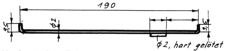
Now all that remains is to secure the rotor head to the main rotor shaft. This is done by clamping the slotted center piece. The middle screw engages with a blind hole in the rotor shaft. We slide the Graupner head onto the Schlüter shaft until the top end is flush with the plastic center piece. When you tighten the center M3 screw, it leaves an indentation on the shaft. We drill a 3-mm-deep blind hole at that point. The center screw is not used to transmit torque from the rotor shaft to the rotor head. This is achieved exclusively through the clamping action of the slotted central piece. It secures the position of the rotor head relative to the shaft, both vertically and in relation to the pitch adjustment slot.
The rest is no problem for an experienced model helicopter pilot. The linkage should be adjusted so that, with the pitch control set to the middle position on the transmitter stick, the mix levers, the blade adjustment levers, and the pitch adjustment levers mounted at the top of the rocker arm are all horizontal. The blade adjustment angle should be +5° at full deflection and -1° to -2° at idle.
Now you’re all set, and I hope you enjoy your upgraded model as much as I have. The adjustable damping allows you to tailor the shaft torque to your preferences and also enables you to set the rotor’s cone angle with great precision. With Graupner rotors, this cone angle is negative when the rotor is at rest. In flight, when lift bends the rotor blades upward and centrifugal force pulls them outward, the cone angle becomes zero. This distinguishes the Graupner rotor from all other industrially manufactured rotor heads. I do not know the reason for this deviation. Upon inquiry, the manufacturer, Bernhard, simply informed me that this was done on the recommendation of Professor Deerschmidt (MBB) and that practical tests had also shown that a cone angle of -1° is optimal when the rotor is at rest. A theoretical justification is lacking.
Together with the weight-matched, laminated rotor blades (order number 74) with a width of 65 mm (they must be shortened by 60 mm), you will experience vibration-free flight and, consequently, a level of control precision that you could only achieve with your old helicopter in its very early days.
Thanks to the lightweight, hollow control paddles, the response is very quick. Nevertheless, the model is also easy for amateurs to control, because every control input is immediately reflected in a change in the helicopter’s attitude before it begins to move.
The model also becomes slightly more docile due to the fact that the linkage lever on the swashplate must be shorter than in the Graupner version. Otherwise, it will hit the starter cone. Anyone who needs the very large aileron deflection for acrobatics must therefore saw off the top of the starter shaft and, from now on,
using a V-belt, as with most other helicopters.
The average helicopter pilot would prefer an even more damped rate of change in the rotor plane for his hover maneuvers. Two lead discs each, 25 mm in diameter and 2 mm thick, mounted on the stabilizer rod, increase the mass on each side by 20 grams. They are attached by cutting radially into the lead discs up to the 4-mm-diameter hole in the center. The discs are then pressed over the
stabilizer rod and glued together with silicone rubber so that the radial cuts are offset by 180°. The discs are also secured to the M4 nut on the inside of the blades using silicone rubber.
With this modification, which can be reversed at any time without tools, the model becomes docile and suitable for beginners. However, that does not mean it does not require constant and coordinated control. It is still a helicopter.
Ernst Bernet


What's New at Leomotion.com

PRIDE AND GOOD IDEAS
 Markus Nussbaumer

News from HEBU

TEAM MANAGER "THIS" BOSSHARD
 Rodito Nussbaumer

ATOM, THE NEW DOUBLE-DECKER FROM CPLR
 Matthias Bosshard

INSIGHTS INTO THE HISTORY OF SEAPLANES

34th HAHNENMOOS ALPINE MODEL AIRPLANE CAMP
Res Dauwalder
CORSAIR F4U – A WARBIRD WITH A MEMORABLE LOOK
Jürgen Rosenberger, Jürgen Prinz
SUMMER FUN 2026 AT MG USTER
Martin Wunderli
F3A EUROPEAN CHAMPIONSHIPS IN ST-MACAIRE, FRANCE
Matthias Bosshard
52. 2026 ALPS CUP
 Emil Giezendanner

HORIZON HOBBY/LEMACO NEWS: MICRO OV-10 BRONCO 645 MM BY E-FLITE

TWIN TOWN PARTNERSHIP
Wolfgang Voeller
EURO CONTEST GLIDER ACRO TOUR AUSTRIA 2026

BY YOUTH, FOR YOUTH
Lorena Betschen
YOU KNOW WHAT I MEAN? 125 YEARS OF THE SWISS AERO CLUB
Emil Giezendanner
SMALL, MODEL-LIKE SAILBOATS
Res Dauwalder
TRY-OUT DAY AT MFV WETTINGEN
Urs Keller
WELCOME, NEW MEMBER!
Andrea Bolliger
FREE FLIGHT IN THE MIDDLE OF SUMMER
Urs Muntwyler
THE PC-21 STORY
Emil Giezendanner
COUPE DES ALPES – OBSERVE AND LEARN
Rodito Nussbaumer
NEWS FROM HEBU
 Julia Bucher

FROM 0 TO 100
Markus Nussbaumer
NOS REGION – A HUB FOR ELECTRIC AVIATION
Emil Giezendanner
MEMORIES
Wolfgang Völler
Have you almost forgotten about aircraft that take off and land vertically?
Emil Giezendanner
70 YEARS OF THE NIDWALDEN MODEL AIRPLANE CLUB
Martin Barmettler