
Construction of a sandwich-core window sash
There are various approaches and methods for building sandwich wings. Sandwich wings offer high profile accuracy and strength, similar to solid fiberglass or carbon-fiber-reinforced plastic (CFRP) structures, but they are usually slightly heavier.
I've had the best results in terms of strength and weight with the design described here.
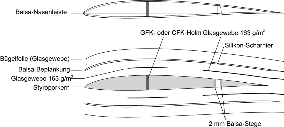
First, the templates for the upper and lower contours must be constructed. I use 2-mm-thick plywood for this. When doing so, the melting zones of the cutting wire (approximately 0.5 mm) must be taken into account. The templates should have an allowance of 15 mm at the front and 20 mm at the back. The cut surfaces must be “polished” with 400-grit sandpaper so that the cutting wire doesn’t get caught.
Next, the upper and lower skin panels are constructed and cut to size. Balsa wood or abachi boards can be used for the skin panels. I opted for 1.5 mm thick balsa wood because it is lighter and easier to work with. Tip: Extend the cut pieces 5 mm toward the rear compared to the original wing dimensions. This gives you a little extra leeway.
Apply pore filler to the inner adhesive side of the upper and lower planking and let it dry. This prevents the wood from absorbing too much resin, which, in the worst case, could diffuse through the wood. Now construct the inner and outer connecting ribs from 2 mm plywood according to the profile drawing.
Now cut the glass or carbon fiber strips to size and, for now, laminate them only to the inside of the upper skin, then let the resin cure. I use 163 GRP fabric for this. Don’t forget to cover the area around the servo cutout with GRP fabric as well.
Once the laminate has cured after about 24 hours, sand it down slightly before continuing so that a secure bond is ensured later on.
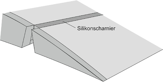
The silicone hinge is attached to the underside of the wing for the flaps and to the top of the wing for the ailerons. In the example described, a plug-in wing equipped with ailerons is being built.
To install the control surface hinge, cut through the skin at the desired location with a sharp utility knife (allow for the 5 mm allowance). Now position the two parts so that a 2 mm-wide gap is created.
Next, mask off the gap lengthwise on the outside with paper masking tape. Since nothing else will stick to the areas where silicone has previously been applied, the surfaces to the left and right of the gap must also be masked with tape. Now the gap can be filled with silicone. I use Elastosil E41 from Wacker for this, available at model shops. After about 2.5 to 3 hours, the silicone has dried and the adhesive tape can be removed.
First, cut out the wing geometry from a 60 mm-thick Styrofoam sheet according to the design drawing (don’t forget to account for the 5 mm allowance). Then, using the templates, cut out first the upper side and then the lower side of the airfoil contour from the cut-to-size Styrofoam block.
This gives you an upper and a lower negative profile template, as well as a wing core. Glue the inner connecting rib onto the wing core. This ensures the highest possible profile accuracy. To be able to sand down a sharp trailing edge later, I cut off a 10-mm-wide strip along the trailing edge of the wing core.
To achieve high profile accuracy and save myself an excessive amount of sanding work, I always build my wings upside down.
To prevent the upper wing skin from sticking to the airfoil template, first place a piece of plastic film cut to fit the shape, then place the prepared upper wing skin onto the inverted upper airfoil template and secure it with adhesive tape. The skin is now coated with resin. When placing the wing core, align the leading edge of the wing core with the leading edge of the skin. A second sheet of plastic film is placed on top to prevent it from sticking to the lower profile template. Then the lower profile template is placed on top, precisely aligned with the leading edge of the profile, and secured with adhesive tape so that the entire “package” cannot slip.
The entire package is now placed inside the vacuum bag, and the opening is sealed airtight. Set the vacuum to approximately -80 to -100 mbar and allow it to cure for about 24 hours.
to prevent this. Then place the lower profile template on top, align it precisely with the front edge of the profile, and secure it with adhesive tape so that the entire “package” cannot slip.
The entire package is now placed inside the vacuum bag, and the opening is sealed airtight. Set the vacuum to approximately -80 to -100 mbar and allow it to cure for about 24 hours.
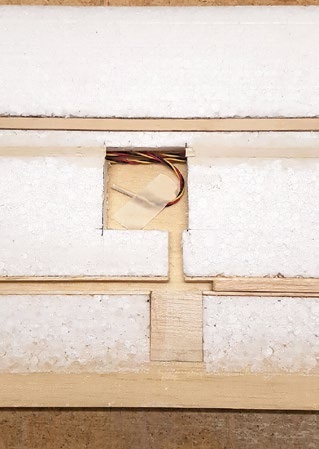
To reinforce the rudder linkage, a balsa wedge should be fitted and glued in place.
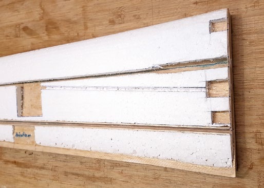
The servo cable is now inserted into the prepared channel. Make sure the cable is long enough to allow for some slack. Next, seal the servo channel with a 1.5 mm strip of balsa wood to prevent resin from seeping in later and gluing the cable in place.
The cutouts for installing the servo, the spar, the aileron struts, the servo cable, and the balsa blocks for the locking pins must be cut and broken out of the Styrofoam as precisely as possible using a sharp utility knife.
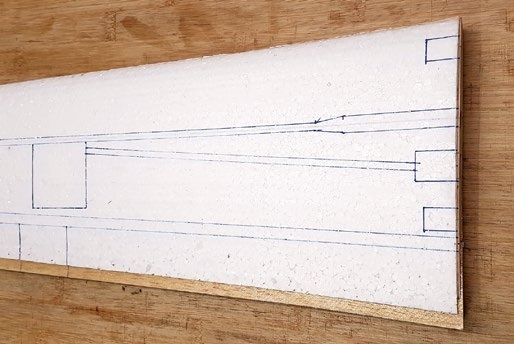
Now comes what is probably the most stressful part of the job.
First, I’ll cut the opening out of the lower skin, matching it to the servo cutout in the Styrofoam.
First, apply resin to the pre-fabricated spar, then lay the prepared fiberglass (or carbon fiber) strips on top. Next, coat the entire surface with resin. Make sure the fabric is thoroughly saturated with resin. Next, place the lower skin on top, making sure it’s precisely aligned.
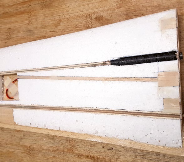
Now fit and insert the balsa blocks for the locking pins.
Next, the balsa struts must be glued into the cutout. The silicone hinge should be positioned in the center of the cutout. To do this, I cut balsa strips to a precise fit of 2 mm. I set the spacing between them to 5 mm. To secure the balsa strips in place on the sides, I slide a 5-mm-wide balsa strip between them, which I remove again after the strips are glued in place.
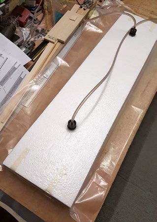
Place the entire package into the vacuum bag. Seal the bag airtight and set the vacuum to -80 to -100 mbar again. After about 24 hours, the package can be unpacked.
To prevent the wing from sticking to the profile templates, place the cut-to-size plastic sheets underneath and on top of the wing.
Now place the lower profile template on the wing, align it precisely, and secure it with tape so that nothing can shift.
Now all that’s left is to glue on the leading edge, the connecting rib, and the wing tip. Take special care when sanding the leading edge. Make sure to create an even curve. Then trim the trailing edge of the wing to the exact geometric dimensions and sand it down according to the selected airfoil. You can sand down to the laminate, resulting in a relatively sharp trailing edge, which reduces aerodynamic drag. When sanding the connecting rib, ensure it has the desired bevel for the V-shape. In most cases, some additional finishing is required to achieve a precise, smooth surface that closely matches the airfoil profile. Exercise caution when sanding, as sanding errors can occur quickly and are difficult to correct. Finally, the ailerons must be cut out. It is advisable to apply appropriate markings beforehand to ensure the clearance between the aileron spars is precise.
This construction method is generally suitable for all model aircraft. However, taking into account the expected forces, the dimensions of the spar, the rib spacing, and any additional auxiliary spars must be adjusted or accounted for accordingly.
The instructions for ironing on the reinforcement film, applying a clear coat to the wing surfaces, or building a fiberglass fuselage are beyond the scope of this article and will be covered in separate articles.


TEAM MANAGER "THIS" BOSSHARD
 Rodito Nussbaumer

F3A EUROPEAN CHAMPIONSHIPS IN ST-MACAIRE, FRANCE
 Matthias Bosshard

News from HEBU

YOU KNOW WHAT I MEAN? 125 YEARS OF THE SWISS AERO CLUB
 Emil Giezendanner

SUMMER FUN 2026 AT MG USTER
Martin Wunderli
TRY-OUT DAY AT MFV WETTINGEN
Urs Keller
52. 2026 ALPS CUP
Emil Giezendanner
BY YOUTH, FOR YOUTH
Lorena Betschen
CORSAIR F4U – A WARBIRD WITH A MEMORABLE LOOK
Jürgen Rosenberger, Jürgen Prinz
SMALL, MODEL-LIKE SAILBOATS
Res Dauwalder
What's New at Leomotion.com

ATOM, THE NEW DOUBLE-DECKER FROM CPLR
Matthias Bosshard
INSIGHTS INTO THE HISTORY OF SEAPLANES

34th HAHNENMOOS ALPINE MODEL AIRPLANE CAMP
Res Dauwalder
HORIZON HOBBY/LEMACO NEWS: MICRO OV-10 BRONCO 645 MM BY E-FLITE

COUPE DES ALPES – OBSERVE AND LEARN
Rodito Nussbaumer
PRIDE AND GOOD IDEAS
 Markus Nussbaumer

EURO CONTEST GLIDER ACRO TOUR AUSTRIA 2026

FREE FLIGHT IN THE MIDDLE OF SUMMER
Urs Muntwyler
THE PC-21 STORY
Emil Giezendanner
TWIN TOWN PARTNERSHIP
Wolfgang Voeller
WELCOME, NEW MEMBER!
Andrea Bolliger
NEWS FROM HEBU
 Julia Bucher

FROM 0 TO 100
Markus Nussbaumer
MEMORIES
Wolfgang Völler
NOS REGION – A HUB FOR ELECTRIC AVIATION
Emil Giezendanner
Have you almost forgotten about aircraft that take off and land vertically?
Emil Giezendanner
70 YEARS OF THE NIDWALDEN MODEL AIRPLANE CLUB
Martin Barmettler