
Schnuppi
Something for opponents of electric aircraft and aerobatics experts who can't afford expensive internal combustion engines.
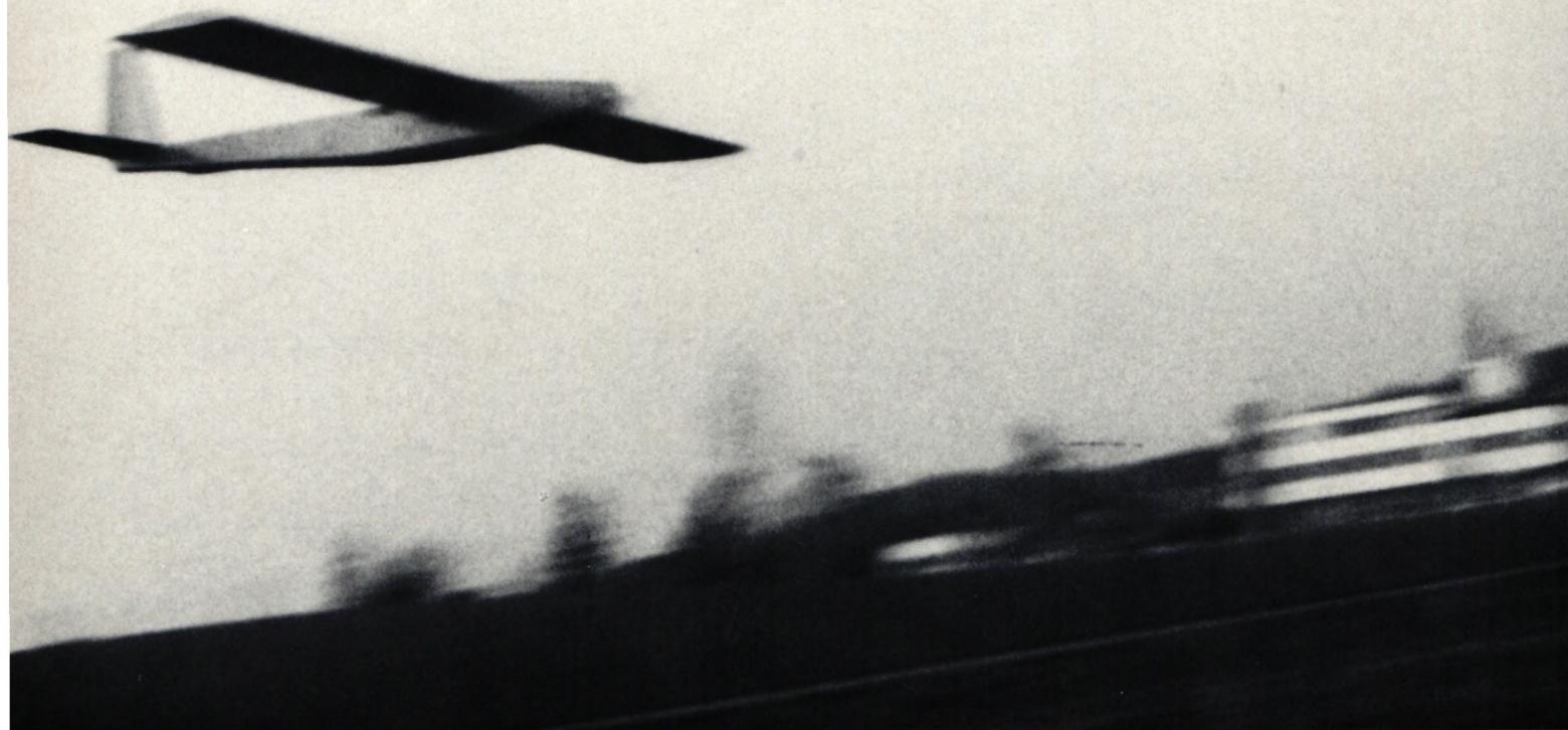
When I started designing the Schnuppi, I intended it to be an inexpensive sports model with ailerons.
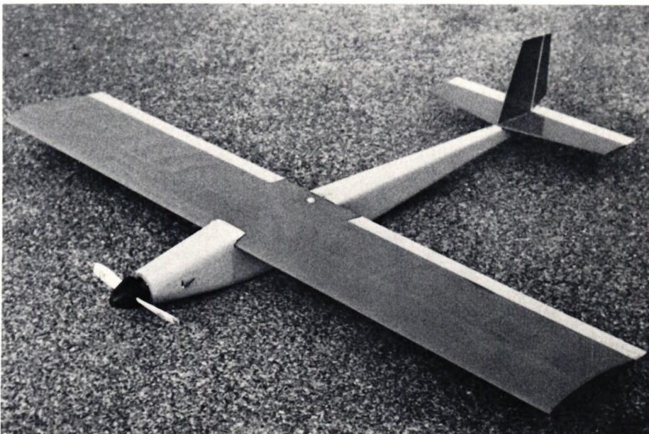
Somehow, though, it turned into a speedster fully capable of aerobatics that far exceeded all expectations.
At the outset, the following specifications were in place:
Jumbo 540 motor, approx. Fr. 17. —
7-cell flight battery, approx. Fr. 50. —
Taipan 7 x 6 propeller
Balsa wood board, 1050 mm long
Receiver unit weighing 210 grams (2 servos and a Geist switch)
The *Schnuppi* was built around these individual parts. The 1050mm wingspan comes from the fact that the balsa strips are exactly this length... The Jumbo 540 motor is about 30g lighter and, with 7 cells, has roughly the same RPM (in flight) as a Jumbo 550 with 8 to 9 cells. However, most electric planes use 7-cell batteries because they can be charged quickly directly from a car battery.
Because the *Schnuppi* has a high flight speed, its power consumption is quite low, resulting in long flight times!
The *Schnuppi*’s flight characteristics exceeded all expectations. For example,
, for example, 3 horizontal rolls in a row or 2 consecutive loops (forward!) can be performed; even longer tail-down aerobatics are no problem!
Since the *Schnuppi* generated an unexpectedly high level of interest at several competitions and events, I decided to draw up a construction plan and write a (modest) set of building instructions.
Fuselage Construction
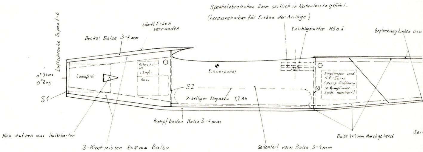
As the observant reader will notice, there is no top view of the fuselage on the construction plan. This is not necessary at all, since the fuselage is assembled freely (in the air). First, glue the front and rear sections of the fuselage together at the joints on the workboard. Next, glue the triangular or rectangular strips to the sides of the fuselage and place a nylon strip over the joint. (Caution! Make sure that the left and right sides are made of wood of equal hardness; otherwise, the fuselage will warp!) The finished fuselage sides are glued together at the rear and secured with pins or masking tape. Only then is the rear main rib glued in place and also held in position with pins and masking tape. Next comes the front main rib, and finally the motor rib, which should have 0 degrees of camber and 0 degrees of dihedral.
Once everything has dried, all that’s left is to attach the corresponding upper and lower fuselage panels (also secure them with masking tape). How much the finished fuselage blank should be sanded down depends on the individual model builder. In any case, the front section should be rounded off generously; it doesn’t matter if the nose frame loses its corners.
Depending on the wing mounting method, the guides for the propeller plate or the round dowels for the rubber rings are then fitted.
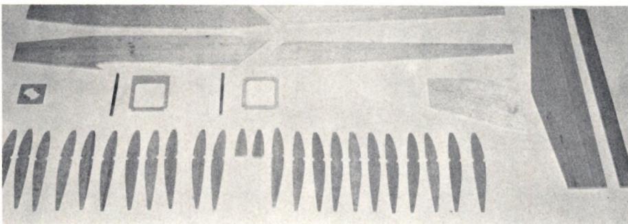
The greatest attention should be paid to the wing construction. For the wing, choose wood that is as warp-resistant as possible! Protect the plan with plastic sheeting, then pin the lower main spar and a 3-mm-thick support strip—positioned 78 mm behind the main spar—to the plan. Then glue the ribs to the lower main spar and secure them with pins. If the wing is to be fastened with screws and dowels, do not glue the two center half-ribs (to the left and right of the dowel) in place yet. Next, fit and glue the box sections in place (the grain direction must be vertical!). While the glue is drying, the nose spar can be installed. Caution: this
SCHNUPPI
Design: H. Sommerauer
This is a somewhat tricky task! Place a pin in front of each rib to press the nose spar into the cutout. The nose spar joints should be re-glued once they have dried. Glue the tail spar in place as well, making sure it is flush with the ends of the ribs. By now, the wooden frames should be dry enough that the upper main spar can be glued in place.
Fitting the wing dowel is done as follows: Exactly in the center of the middle wooden box, drill a 5 mm hole beneath the upper main wood. Insert the dowel so that it crosses the nose spar at the front. At this intersection, file a slot into the top of the nose strut that is the same width as the dowel, and file a slot into the bottom of the dowel that is the same width as the nose strut, until the dowel is at the same height as the nose strut. Now glue the dowel in place and attach the half-ribs to the left and right of it.
Once everything is thoroughly (!) dry, remove the frame from the workboard and carefully remove any excess glue.
The planking is applied as follows:
The wing is clamped face down onto the workbench; a strip of appropriate thickness is placed under the trailing edge spar. The skin is then applied using contact adhesive. First press it against the main spar, then gradually pull it toward the leading edge spar. Do not use wood that is too brittle for the planking! The top surface is planked in exactly the same way; it is important that the wing is secured to the board without any warping!
Now glue the Bowden cables in place using epoxy adhesive (Caution: do not use 5-minute epoxy, otherwise the tubes will kink due to the heat!). Gluing the leading edge skin, rib coverings, and wing tips with contact adhesive largely completes the wing construction. The trailing edge of the wing is now sanded down so that it is exactly flush with the aileron. The center section of the trailing edge is glued in place, and the hole for the nylon screw is drilled. After careful sanding (the leading edge of the airfoil should remain fairly pointed), the wing and ailerons can be covered with film. Waterproof adhesive tape (Tesapack) serves as the aileron hinge.
The tail surfaces are drilled and sanded smooth. After they have been covered, they are glued to the fuselage at an angle (5-minute epoxy). The fuselage can be covered with paper or plastic sheeting as desired. The wing is fitted into the fuselage. To do this, drill the hole for the dowel in the front main frame slightly too small, then use a file to adjust it. Drill the appropriate hole in the small block for the drive nut. At the front of the fuselage, the
Glue the cooling hoods together using drawing paper. The end of the fuselage must remain open so that the cooling air can escape.
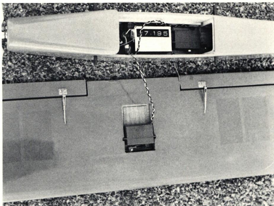
You may encounter some problems when installing the control system. The best approach is to cut an opening in the underside of the fuselage behind the flight battery compartment, through which the (mini) elevator servo and the receiver can be installed. To save the most space, attach the components to the fuselage walls using double-sided tape. Do not use foam rubber,
as this could impair cooling! The Bowden cable core for the ailerons is fed all the way through. In the middle, a special fitting (from Goldberg 0.AE.) is threaded onto the Bowden cable core and screwed into place at the center. The servo is glued horizontally onto the reinforced upper skin, and the clevis of the fitting is hooked onto the servo. The control surface hinges can be made from 1.5 mm plywood. An electronic switch is recommended for the motor switch (due to space constraints). The receiver battery should not exceed 225 mAh (for space and weight reasons).
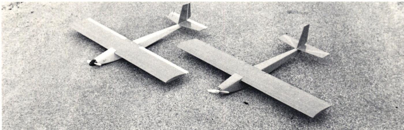
If the center of gravity is correct and the wing is built without warping, nothing stands in the way of the maiden flight. The Schnuppi should be launched into the air with a powerful swing. Be careful—the Schnuppi’s controls respond quite directly! It is precisely this characteristic that allows for aerobatics in the tightest of spaces. Landing is a breeze; you can run the Schnuppi right down to empty before it touches down gently.
Hopefully you’ll have lots of fun with your Schnuppi!
The author wishes you no broken spars or ribs.
The “Schnuppi” plans, including assembly instructions, are available for sFr. 12.50 from: H. Sommerauer, Waserstr. 21, 8053 Zurich.


TEAM MANAGER "THIS" BOSSHARD
 Rodito Nussbaumer

SUMMER FUN 2026 AT MG USTER
Martin Wunderli
TRY-OUT DAY AT MFV WETTINGEN
Urs Keller
52. 2026 ALPS CUP
 Emil Giezendanner

ATOM, THE NEW DOUBLE-DECKER FROM CPLR
 Matthias Bosshard

INSIGHTS INTO THE HISTORY OF SEAPLANES

34th HAHNENMOOS ALPINE MODEL AIRPLANE CAMP
Res Dauwalder
CORSAIR F4U – A WARBIRD WITH A MEMORABLE LOOK
Jürgen Rosenberger, Jürgen Prinz
SMALL, MODEL-LIKE SAILBOATS
Res Dauwalder
F3A EUROPEAN CHAMPIONSHIPS IN ST-MACAIRE, FRANCE
Matthias Bosshard
What's New at Leomotion.com

HORIZON HOBBY/LEMACO NEWS: MICRO OV-10 BRONCO 645 MM BY E-FLITE

PRIDE AND GOOD IDEAS
 Markus Nussbaumer

News from HEBU

BY YOUTH, FOR YOUTH
Lorena Betschen
YOU KNOW WHAT I MEAN? 125 YEARS OF THE SWISS AERO CLUB
Emil Giezendanner
FREE FLIGHT IN THE MIDDLE OF SUMMER
Urs Muntwyler
THE PC-21 STORY
Emil Giezendanner
TWIN TOWN PARTNERSHIP
Wolfgang Voeller
EURO CONTEST GLIDER ACRO TOUR AUSTRIA 2026

WELCOME, NEW MEMBER!
Andrea Bolliger
COUPE DES ALPES – OBSERVE AND LEARN
Rodito Nussbaumer
NEWS FROM HEBU
 Julia Bucher

FROM 0 TO 100
Markus Nussbaumer
MEMORIES
Wolfgang Völler
NOS REGION – A HUB FOR ELECTRIC AVIATION
Emil Giezendanner
Have you almost forgotten about aircraft that take off and land vertically?
Emil Giezendanner
70 YEARS OF THE NIDWALDEN MODEL AIRPLANE CLUB
Martin Barmettler