
Solar-Powered Flight: Working with Solar Cells
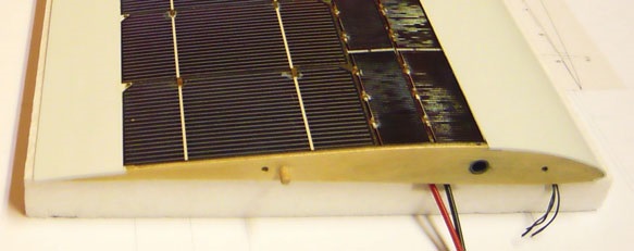
Solar cells are extremely fragile. This applies both during the construction phase of the solar wing and during subsequent model transport and flight operations. In Serge Encoua’s “EZE Solar Glider 3” model (see MFS No. 4/2018), the delicate silicon wafers are well protected and integrated into the wing. My subsequent remarks assume that the solar cells will be arranged on the upper surface of the wing, where they are exposed to direct sunlight and cooled by the airflow during flight.¹
My first experiences with solar cells, ten years ago, were sobering. Many of the silicon wafers—only 0.3 mm thick—were already defective during the construction of the wing: careless handling in the workshop, a surface that was too soft during soldering, excessive pressure from the soldering iron, burnt silver contact points due to prolonged exposure to heat, and fractures when bonding them to the ribs, etc.
At that time, I opted for the high-lift profile S4083 (Selig), which Oskar Czepa also used on his “Quäntchen.” While this was aerodynamically optimal, it was extremely complex from a structural engineering standpoint. By using Schindelstrings2, arranged in a polygonal pattern, I was able to counteract the high curvature in the forward section of the airfoil.
After my “Sunnevogu” made a forced landing in a cornfield at the homebuilt airshow in Huttwil (propulsion failure, transmission problem), the first cells had to be replaced—and a screwdriver that slipped out of my hand even fell onto the wing. As a result, the spare parts I’d purchased as a precaution were quickly used up. Neither Schindelstrings nor cell blanks cut from 100 × 100 mm wafers were available anymore.
Then the report on the “EZE Solar Glider” appeared. This model uses neither a special solar flight profile³ nor a high-lift profile, but rather a modern HLG profile! That was the motivation to build a new solar wing—but this time, a better one!
The AG16 profile (Mark Drela) used in the “EZE Solar Glider 3” has a uniform curvature over a large portion of its upper surface and is therefore well-suited for mounting large-area solar cells on top of the profile.
The 0.25 mm-thick silicon wafers allow for slight bending before they break. A slight mechanical preload even has the advantage of allowing the solar cells to withstand slightly more pressure on the surface. There’s no way around testing (and possibly some losses) here. Bending tests had shown that the increase in profile thickness from 7.12% to 8.1%—desired for structural reasons (rib wings)—is entirely feasible.
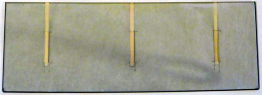
Reinforcing the solar cells on the underside with lacquered Japanese paper increases their breaking strength with minimal added weight:
| Solar cell 156 mm × 52 mm | 4.0 g/cell |
| Additional weight from Japico on the underside | 0.3 g/cell |
| Weight of solar cell connector | 0.4 g/cell |
The Japico 21 g/m² Japanese paper, moistened with water (with cutouts at the solder pads), is glued to the
and, after drying, is coated with another layer of varnish. The cutouts for the solder pads must, of course, remain varnish-free!
Due to the tension of the mounting paper during the drying process, the previously flat solar cell bends in the desired direction as intended.
The EU Directive on the Restriction of Hazardous Substances (RoHS) has prohibited the electronics industry from using lead-based solders since 2005, and as a result, the soft solders available today for hobbyists are mostly lead-free tin alloys (1,2).
The “special solder” containing silver (2) recommended by my solar cell supplier does have a lower melting point than today’s industry standard, but even with it, the delicate, silver-coated contact points on the solar cells are quickly burned away.
| Solder (solder wire) | Alloy | RoHS | Melting point | Soldering temperature | Remarks |
|---|---|---|---|---|---|
| 1 Tin (Balver SN100C) | SnCu0.7Ni | Yes | 227°C | 350°C | Industry Standard |
| 2 Tin with silver content (Balver SN97C) | SnAg3.0Cu0.5 | Yes | 217–218°C | 350°C | Lemo Solar Recommendation |
| 3 Tin-lead, silver content (Loctite SN62 5C) | Sn62Pb36Ag2 | no | 179°C | 300°C | Repairs, special applications |
| 4 Tin-Bismuth Alloy (ChipQuik SMDSWLT.040) | Bi57Sn42Ag1 | Yes | 138°C | > 250°C | Low-temperature solder |
It works better with the tin-lead alloy optimized for a minimum melting temperature and containing 2% silver (3), which I also used ten years ago for the solar cells of that time. Such solders are still available for special applications. I’m convinced that a few grams of this solder won’t jeopardize RoHS compliance!
But soldering only becomes truly stress-free with the low-temperature solder made from a bismuth-tin-silver alloy (4), such as the 1-mm-thick solder wire offered by Chipquik (supplier: DigiKey). This material is very expensive, so it makes sense to use it only for soldering the silver-coated contact points.
The flux contained in the core of a solder wire ensures that the tin bonds well with the solder pads. For the fine, silver-coated solder pads on the solar cells, however, additional pretreatment with a flux pen is recommended. With two firm strokes, the soldering surface is wetted and the silver oxide is scraped away at the same time. I achieved good soldering results with both brands I tested:
| Flux pen | Quantity | Supplier |
|---|---|---|
| Chipquik CQ4LF Kester #951 | 10 ml 10 ml | Digikey AliExpress |
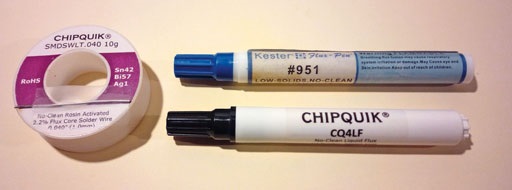
Low-temperature solder and flux sticks.
A temperature-controlled electronic soldering iron (e.g., Weller WHS 40) is absolutely necessary.
Solar cell connectors are tin-plated, flat copper conductors used to solder individual cells together to form a solar module. Their flat design ensures that only minimal bending forces are exerted on the fragile silicon wafers.
To pre-assemble the strip elements, I fashioned a crimping tool out of a pair of small flat-nose pliers. I removed any contaminants and adhesive residue from attaching the paper reinforcement using rubbing alcohol and cotton swabs. Next, I applied flux with a flux pen, added a small amount of solder, and then soldered the strip element in place. If you don’t want to burn your fingers, use tweezers for this step.
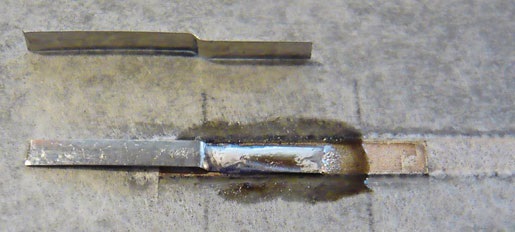
Attaching strip elements (positive and negative terminals) to both sides before installation has the advantage that no delicate soldering process is required once the panel is installed. You simply solder the strip elements together. Replacing a broken cell should also be easy—
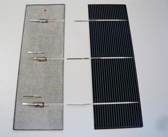
could be (fortunately, this hasn't happened yet).
Following the instructions from my solar cell supplier, I attached the solar cells to the ribs using self-adhesive foam rubber strips approximately 1 mm thick (see Lemo Solar, Solar Cell Manual). Contrary to the recommendations, however, the side exposed to sunlight was not coated with a protective varnish. →
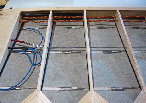
The greatest risk of damage to the solar wing occurs during transport to the model airfield. Styrofoam molds on the top and bottom of the two wing halves, held together with Velcro strips, have proven to be very effective.
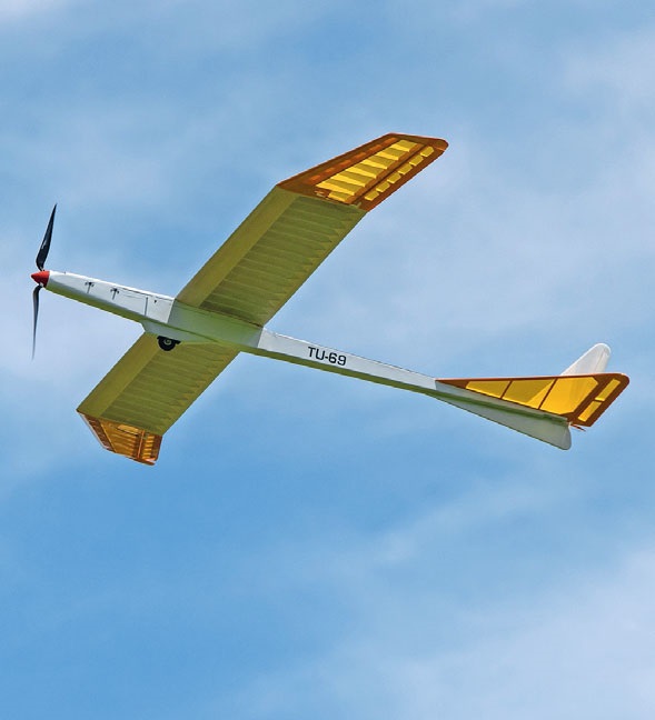
Finally, the reward for all those hours of work: The
model climbs gently into the air after a hand launch. Propulsion and the RC power supply are provided solely by sunlight hitting the wings; only a small buffer capacitor of 10F (5 V/approx. 3 mAh) for the receiver and servos offers some hope that, in the event of an unexpected solar eclipse, the model can still be landed safely.
1) Improved electrical efficiency of the cells at low temperatures
2) Satellite solar cells measuring 20×40 and 20×60 mm (Weissgerber)
3) See “Solar-X4” by Helmut Schenk or “Silizi Solar” by Horst Groner


News from HEBU

TEAM MANAGER "THIS" BOSSHARD
 Rodito Nussbaumer

SUMMER FUN 2026 AT MG USTER
Martin Wunderli
SMALL, MODEL-LIKE SAILBOATS
Res Dauwalder
TRY-OUT DAY AT MFV WETTINGEN
Urs Keller
What's New at Leomotion.com

52. 2026 ALPS CUP
 Emil Giezendanner

ATOM, THE NEW DOUBLE-DECKER FROM CPLR
 Matthias Bosshard

INSIGHTS INTO THE HISTORY OF SEAPLANES

YOU KNOW WHAT I MEAN? 125 YEARS OF THE SWISS AERO CLUB
Emil Giezendanner
34th HAHNENMOOS ALPINE MODEL AIRPLANE CAMP
Res Dauwalder
CORSAIR F4U – A WARBIRD WITH A MEMORABLE LOOK
Jürgen Rosenberger, Jürgen Prinz
F3A EUROPEAN CHAMPIONSHIPS IN ST-MACAIRE, FRANCE
Matthias Bosshard
HORIZON HOBBY/LEMACO NEWS: MICRO OV-10 BRONCO 645 MM BY E-FLITE

PRIDE AND GOOD IDEAS
 Markus Nussbaumer

BY YOUTH, FOR YOUTH
Lorena Betschen
FREE FLIGHT IN THE MIDDLE OF SUMMER
Urs Muntwyler
THE PC-21 STORY
Emil Giezendanner
TWIN TOWN PARTNERSHIP
Wolfgang Voeller
EURO CONTEST GLIDER ACRO TOUR AUSTRIA 2026

WELCOME, NEW MEMBER!
Andrea Bolliger
COUPE DES ALPES – OBSERVE AND LEARN
Rodito Nussbaumer
NEWS FROM HEBU
 Julia Bucher

FROM 0 TO 100
Markus Nussbaumer
MEMORIES
Wolfgang Völler
NOS REGION – A HUB FOR ELECTRIC AVIATION
Emil Giezendanner
Have you almost forgotten about aircraft that take off and land vertically?
Emil Giezendanner
70 YEARS OF THE NIDWALDEN MODEL AIRPLANE CLUB
Martin Barmettler