
A Corsair at School
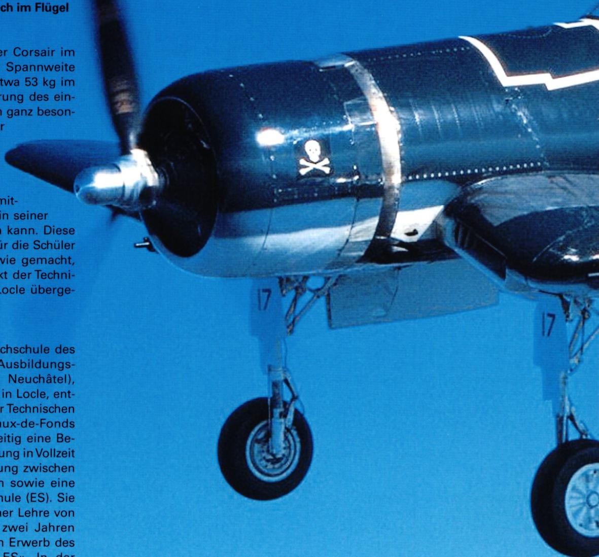
The Corsair F40 is an airplane that was state-of-the-art in its day. It can be adapted to all scales, from the foam version to “a bit larger.” This famous aircraft from the Pacific War, which has made a comeback thanks to a team of tireless innovators and Pappy Boyington, certainly owes part of its success to its distinctive appearance, featuring its foldable wings with a double-V configuration. Another special feature for model enthusiasts is its kinematically complex landing gear, as the landing gear leg rotates 100°, while the wheel simultaneously rotates 90° to retract flat into the wing.
When building a 1:3 scale model of a Corsair with a wingspan of 3.60 m and an in-flight weight of approximately 53 kg, the retractable landing gear requires a very special design to ensure that neither the model’s service life nor the safety of spectators is compromised. It requires manufacturing methods that a model builder cannot implement in his workshop. This educational exercise is ideal for students at a mechanical engineering school, which is why the project was entrusted to the CIFOM Technical School in Locle.
The CIFOM (Interregional Training Center of the Neuchâtel Mountain Region) Higher Technical School, located primarily in Le Locle, was formed through a merger of the technical schools in La Chaux-de-Fonds and Le Locle. It functions both as a vocational school offering full-time instruction and work-study programs, and as a Higher Technical School (ES). After a four-year apprenticeship followed by two years of full-time study at the school, it prepares its students to earn the title of “ES Diploma Technician.” In the microtechnology department, under the direction of Professor Alain Krebs,
, several students successfully designed and then manufactured the retractable landing gear.
This project highlights the challenge technical schools face in carrying out a concrete project: the comprehensive knowledge required for its implementation
The goal of such a project is precisely what the student strives to achieve during the course of his or her training. It therefore makes no sense to give a first-year student a set of specifications and require him or her to produce a kinematic design for various projects.
Nor is it reasonable to require them to produce a CAD drawing, create a design, perform design calculations, comply with standards, find suppliers for specific parts, understand how an electric motor works, or machine parts with knowledge of the materials to be used. Furthermore, orthographic drawing skills are required to submit a work report. It is therefore much better to assign such a project at the end of the training period, as a culmination of the six years of training. In any case, the time available for such a project remains limited for the students, because a significant portion of the training is devoted to acquiring theoretical knowledge, such as material strength or new machining methods.
The second major problem is the use of software for design and material processing. In fact, becoming familiar with such complex tools requires many hours of work, which students—with their already packed curriculum—simply do not have available. Given the sheer volume of work, the role of the instructor takes on a new dimension, as their support is crucial for the students—they assist them and often complete a necessary step for each phase of the work before the next stage can begin.
The first step is to build a model of the Corsair F4U’s landing gear, using, for example, a small Robart landing gear, while retaining the kinematics and aesthetics of the original. Control is electric, using a lead screw, in contrast to the prototype’s pneumatic operation. The student must prepare complete documentation for the project. For educational reasons, CNC machining is preferred, and solutions such as cutting and bending should be avoided.
- Analysis of the fundamentals and possible solutions. Select one of them as the valid option.
- Search for suppliers of prefabricated parts and request quotes.
- Execution of the design and functional drawings of the structure using Autodesk Inventor 2009.
- Preparation of a complete design report, including the specifications, design drafts, scaled-down drawings, supplier parts with their quotes, calculations, and settings.
- Presentation of an engaging PowerPoint slideshow of the entire project, highlighting key milestones not necessarily included in the design report.
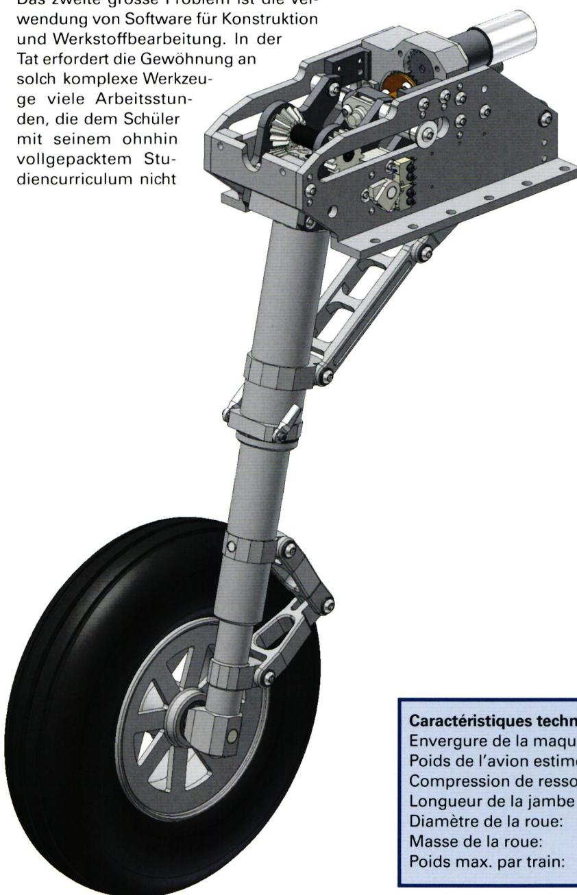
| Wingspan of the model: | 3.60 m |
| Estimated weight of the aircraft (empty): | 50 kg |
| Landing gear spring compression: | 5–6 mm under a load of 550 N |
| Length of the landing gear leg: | 300 mm (wheel axle joint) |
| Wheel diameter: | 200 mm |
| Wheel weight: | 650 g |
| Maximum weight per landing gear: | about 1.4 kg |
Excerpted and adapted from the report by student Loïc Grezet:
“I decided to start the design based on a ball screw drive system. I connected the screw to a motor mounted above it to save space. Then I turned my attention to the swivel arm. I started with a gearbox mounted on the side of the arm. To save vertical space, I offset one gear from the axis, which allowed me to save a significant amount of space. The design of the springs and the mounting of the entire system posed no particular problems. Two brackets support the entire system. I made my landing gear as light as possible to meet the specifications as closely as possible. The aesthetically pleasing brackets caused some problems because there isn’t much space in the wing, and a large clearance is required when the arm is extended. The wheel-counter-rotation system is almost identical to that of the base model. Implementing my system was a laborious process; the biggest problem was the space required.”
Extending the landing gear: A remote-controlled motor drives the gearboxes and the spindle. Using an actuator fork, the spindle and its sleeve push the landing gear, causing a rotational movement around the arm’s pivot point; this rotation corresponds to 100°. A gearbox is mounted on the fixed pivot axis of the landing gear leg. It actuates a gear train (on the arm side) that allows the wheel to rotate 90°.
Once the landing gear has completed its full rotation, the locking fork engages between the spindle drive sleeve and a stop (the same system used when retracting the landing gear). This system allows the landing gear axle to be locked in either the extended or retracted position. At the same time, the spindle sleeve makes contact with a limit switch, causing the motor to stop. A compression spring is built into the system’s arm to dampen shocks and jolts during landing. An articulated anti-rotation system (to counteract impacts and vibrations) is provided on the axle behind the wheel.
Retracting the landing gear: The motor restarts in the opposite direction, causing the drive leg to rotate 100°. With the help of the gearbox, the wheel rotates 90° to retract under the aircraft wing. The same locking mechanism used during extension is then employed, and a second switch shuts off the motor.
Adjustments: The limit switches can be adjusted using the two screws on the switch mounting plate. Simply loosen them slightly and slide the switch into the correct contact position. The bevel gears must be adjusted when assembling the landing gear. To do this, simply apply a small amount of Prussian blue to the teeth and turn them a few revolutions (the two points on the bevels must be in the same position). Simply insert or remove a few spacer washers at the level of the conical horizontal gear.
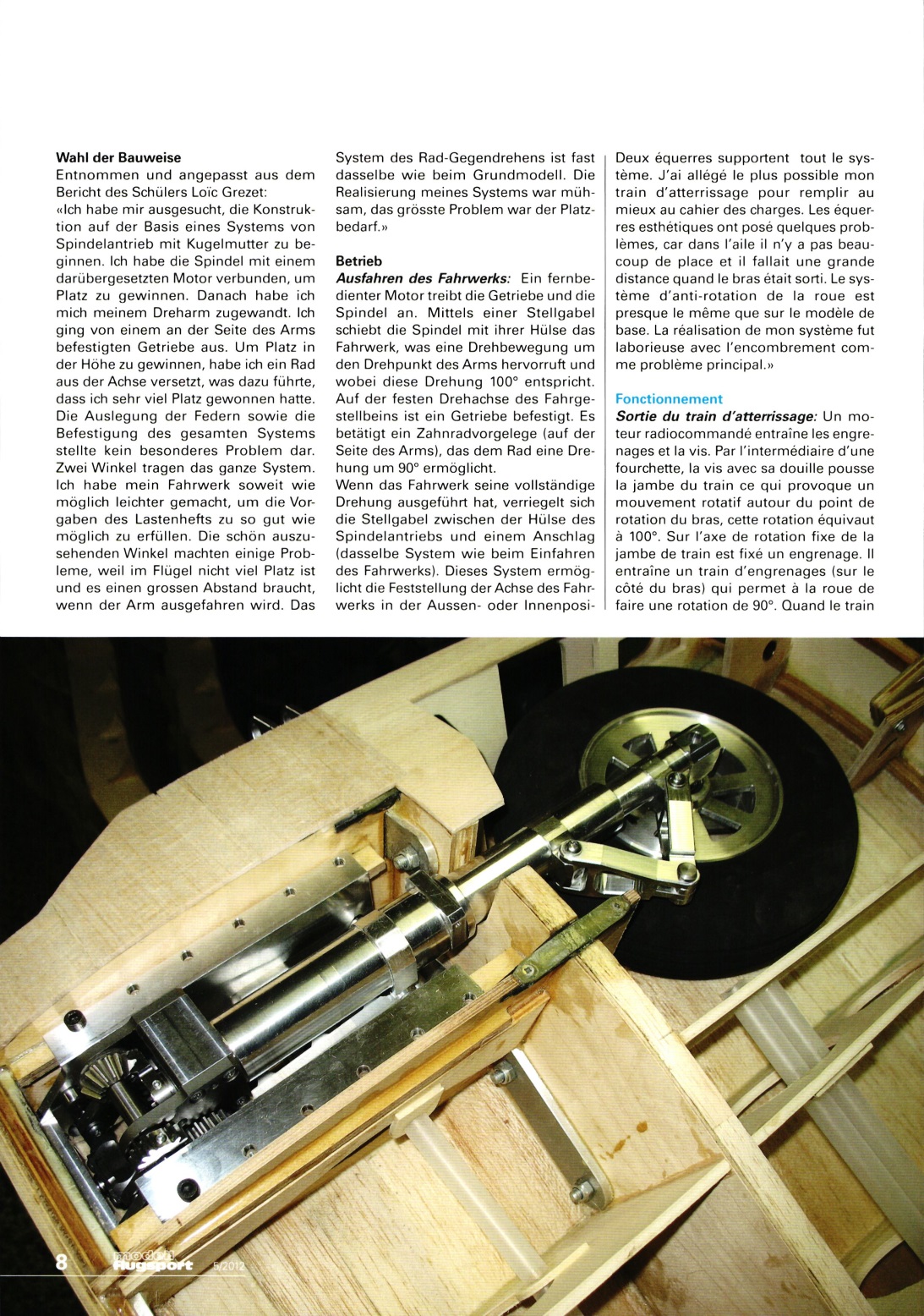
The system operates in accordance with the specifications. It might be possible to find a system with less play in the gears for transmitting the 90° movement. For economic reasons, a simple drive screw was chosen for the chassis instead of a spindle drive.
The inner leg of the chassis, which rotates 90°, is made of solid material. It could be hollowed out to save weight. The distance between the pivot point and the wheel axle (300 mm) can be easily adjusted: simply reduce the distance between the main axle and the inner axle.
The first two landing gear prototypes were mounted on the Corsairs during the design phase to finalize their mounting and attachment to the airframe. The Corsair still requires many months of work before it can take to the skies. The first flights are scheduled for early 2013.
Once again, this project demonstrates that model building touches on all the disciplines taught at a technical vocational school—and even more beyond that. It makes these subjects more appealing because students gain knowledge much more effectively through hands-on applications. The students’ enthusiasm is telling—almost effusive—when they talk about their work, the problems they’ve encountered, and the solutions they’ve found. Their motivation develops all on its own. The work is not limited to technical aspects but also incorporates spelling, oral presentation, and the defense of ideas. One could also consider group work, similar to what students will encounter in the industry. Structured instruction on a topic could also make language learning easier. Why not go even further and expect a student to deliver their presentation in German or English? Clearly, the project makes it possible to give concrete form to the theoretical aspect of instruction and to think ahead, since the student is confronted with questions they will only tackle later on. The Corsair retractable landing gear project thus touches on a wide range of educational topics. Model builders should not be under any illusions: the cost of manufacturing this landing gear is beyond the budget of most model builders. One should admire this 3.60-meter Corsair all the more, keeping in mind the breadth of specialized skills required for such a project.


TEAM MANAGER "THIS" BOSSHARD
 Rodito Nussbaumer

SUMMER FUN 2026 AT MG USTER
Martin Wunderli
52. 2026 ALPS CUP
 Emil Giezendanner

ATOM, THE NEW DOUBLE-DECKER FROM CPLR
 Matthias Bosshard

INSIGHTS INTO THE HISTORY OF SEAPLANES

34th HAHNENMOOS ALPINE MODEL AIRPLANE CAMP
Res Dauwalder
CORSAIR F4U – A WARBIRD WITH A MEMORABLE LOOK
Jürgen Rosenberger, Jürgen Prinz
SMALL, MODEL-LIKE SAILBOATS
Res Dauwalder
F3A EUROPEAN CHAMPIONSHIPS IN ST-MACAIRE, FRANCE
Matthias Bosshard
What's New at Leomotion.com

HORIZON HOBBY/LEMACO NEWS: MICRO OV-10 BRONCO 645 MM BY E-FLITE

PRIDE AND GOOD IDEAS
 Markus Nussbaumer

News from HEBU

BY YOUTH, FOR YOUTH
Lorena Betschen
YOU KNOW WHAT I MEAN? 125 YEARS OF THE SWISS AERO CLUB
Emil Giezendanner
TRY-OUT DAY AT MFV WETTINGEN
Urs Keller
FREE FLIGHT IN THE MIDDLE OF SUMMER
Urs Muntwyler
THE PC-21 STORY
Emil Giezendanner
TWIN TOWN PARTNERSHIP
Wolfgang Voeller
EURO CONTEST GLIDER ACRO TOUR AUSTRIA 2026

WELCOME, NEW MEMBER!
Andrea Bolliger
COUPE DES ALPES – OBSERVE AND LEARN
Rodito Nussbaumer
NEWS FROM HEBU
 Julia Bucher

FROM 0 TO 100
Markus Nussbaumer
MEMORIES
Wolfgang Völler
NOS REGION – A HUB FOR ELECTRIC AVIATION
Emil Giezendanner
Have you almost forgotten about aircraft that take off and land vertically?
Emil Giezendanner
70 YEARS OF THE NIDWALDEN MODEL AIRPLANE CLUB
Martin Barmettler