
Fuselage constructed using positive shell construction
Since I had already built several wings using the monocoque construction method, it made sense to apply this principle to fuselages as well. Although models built using the monocoque method are available on the market, they are, without exception, in the higher price range. Building a monocoque model yourself can therefore significantly ease the strain on your model-building budget—not to mention the fact that designing and constructing a model from scratch is always an interesting endeavor and provides valuable experience.
While a negative mold for wings can be cut in the traditional way using polystyrene foam, cutting templates, and a heating wire, this is not possible for fuselages due to the spherical curves of the fuselage contour. The effort required to produce a negative mold for a fuselage is therefore considerable and is really only worthwhile if large quantities of fuselages are to be manufactured, as is the case with commercial manufacturers. In my case, the quantity is rarely more than one, so it made sense to try using a positive mold, which is much easier to make.
Since I wasn’t entirely sure whether the project would turn out the way I’d imagined, I first tested the idea on a relatively small model to minimize material loss and waste in case of failure. The most important
steps in building this model—especially the fuselage—are described below.
The plan was to build a small electric aerobatic model with a wingspan or length of 1.2 m and a target weight of 1.1 kg. I decided against using a landing gear, since hand-launching this type of model is no problem and it saves a bit of weight. Based on an assessment of all weight moments, the battery was supposed to be positioned roughly at the calculated center of gravity, though I allowed for a wide range of adjustment to shift the battery for center-of-gravity fine-tuning. Once again, I used the S 8035 airfoil, with a thickness of 14% on the inner section and 12% on the outer section. While it proved to be a bit too docile and,
and consequently too sluggish in sharp maneuvers; however, it has proven quite effective on small models.
The following instructions assume that a 1:1 plan of the entire model has already been created, from which at least the fuselage outline, several cross-sections, and the positions of the frames, wings, and tail surfaces can be determined.
Material: Styrofoam or another rigid foam that can be cut with a hot wire is used. Unlike Styropor, this material can withstand atmospheric pressure during vacuum pressing without deforming. Using the hot wire and, where necessary, cardboard templates, the
individual parts are roughly cut out of rigid foam of suitable thickness, with a slight allowance, with one part for each half of the mold. In my case, I opted for three parts: the front fuselage section (excluding the cowling), the fuselage tube, and the side stabilizer. The half-side mold parts are then joined with a few dots of glue; they should be separable later without damaging the mold. Using a few fuselage cross-section templates, the three parts are now cut (roughly) or sanded into their final shape (Figure 1) and then glued together. I use white glue for this, though it takes a long time to dry in the foam. The seams as well as any “imperfections” can then
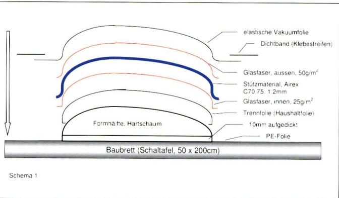
It still needs to be filled with a light-duty putty knife and sanded down completely. Next, the mold halves must be separated again using a sharp knife (Figure 2). At the parting line, both halves are now reinforced with a 10-mm-thick layer of the same rigid foam (see Diagram 1). This is necessary to ensure that the shell halves taper off precisely along the parting line later on. Thanks to how easy and quick the rigid foam is to work with, a mold like this can be completed in a very short time! The fuselage cross-section templates mentioned above are best created at the points on the fuselage where frames will later be inserted into the finished fuselage shell; this also makes these templates suitable for producing precisely fitting frames later on.
Shells: To cut out the components of the shell sandwich—consisting of fiberglass, support material, and fiberglass—it’s worth making a clay
cardboard template (Figure 3). The dimensions for this can be measured directly on one mold half using a measuring tape; it is helpful to draw a reference line on the mold halves and then also on the fiberglass and backing material pieces. In this case, this was the line from the propeller axis to the HLW.
The construction of the shell is shown in Diagram 1: First, the mold half is wrapped in release film (Figure 4). Thin, colorless, and self-releasing plastic wrap from the kitchen has proven effective for this. It’s not possible to completely avoid wrinkles, but that doesn’t matter because they’re on the inside of the shell. I’ve found that using masking tape and PVA release film hasn’t worked as well. Next, the fiberglass inner layer is placed on the mold half and sparingly saturated with resin [1] [2] using the foam roller. Then the support fabric is placed on
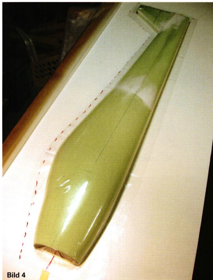
which had previously been covered with the outer layer of fiberglass and also lightly impregnated, is placed on top and secured against slipping with two small nails treated with release wax
. Finally, the highly elastic (that’s the key feature!) and self-separating vacuum film—to which the vacuum hose connection has already been attached—is stretched over the top and secured all around with brown packing tape, as vacuum-tight as possible, i.e., without wrinkles, all the way around the workboard (Figure 5). Now the
1) Epoxy resin + Hardener L, 40-minute pot life
2) All materials are available from Suter Kunststoffe AG, Jegenstorf.
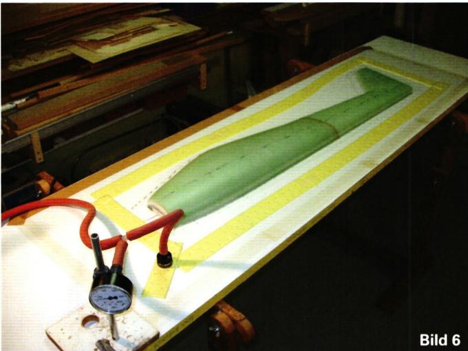
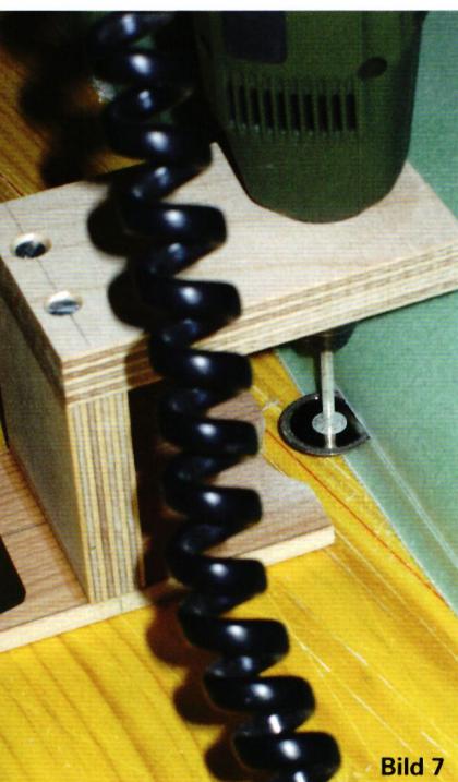
Once the air is evacuated, the vacuum wrap fits neatly and wrinkle-free around the workpiece (Figure 6). Strips of nonwoven fabric or similar material (shown in yellow in the figure) facilitate the removal of air. To speed up the curing process a bit, I heat the entire assembly by placing a “heating blanket” (an unfolded plate warmer) over it. After curing, the vacuum and release films can be removed and the edges trimmed. It is now important to cut away the excess material on the mold halves exactly along the future fuselage line. For this, I use a clamping device for a Dremel with a cutting disc (Figure 7). The shells are placed over the mold once more, and now exactly the
10 mm—the amount by which the mold was thickened—can be cut away all around. The now-routine check on the scale yielded just under 50 g per shell half (Figure 8).
After the areas on the insides of the shells where structural components (frames, etc.) are to be installed, one half of the shell is temporarily secured to the building board (to prevent warping) and glued to the other half with resin and microballoons.
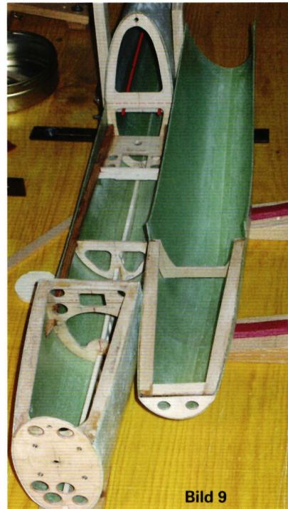
Next, the seam is sanded down, reinforced with a narrow strip of fiberglass (50 g/m²)—for now, only on the outside— the edges of which are lightly filled and sanded (carefully, so as not to sand through the thin fiberglass!), and the entire hull shell is painted with a pore-filling primer and wet-sanded. The result is a surface that looks quite good, even if it can’t quite match the high gloss of shell sections that have been industrially painted and laminated in negative molds. After precise marking, the canopy and cutouts- for the one-piece wing and for the HLW can be cut out, the glass strip (50 g/m²) applied to the inside of the fuselage, and the frames, etc., installed (Figure 9).
The hood was also laminated using a conventional method—that is, not as a fiberglass-reinforced plastic (FRP) shell part—over a positive mold (Figure 10), which also highlights where the shell-positive construction method shown here has its limitations: Parts with a strongly spherical curvature are not possible, as the support material used is not stretchable enough. It would also be conceivable to cut out the support material that becomes superfluous during deformation beforehand, but this would partially negate the simplicity of the described process.
The manufacture of the wing and HLW will not be discussed in detail here. The shells for these are laminated in a negative mold following a procedure already described [3] (Diagram 2), since, due to their non-spherical curvature, they cannot be produced using conventional methods with a hot wire
and cutting ribs. The wing core produced in this process is not used here and can be disposed of immediately.
The upper and lower half-shells are identical due to the symmetry of the profile. The self-separating Mylar film serves to create a smooth, high-gloss surface. Without the film, the surface porosity of the negative mold
be visible on the wing surface.
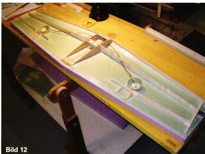
Upon closer inspection (with a magnifying glass) of the two wing and HLW half-shells produced in this way (Figure 11)—which had a surface that looked very nice to the naked eye—I noticed that fine pores had formed between the individual fibers of the glass fabric. Since I covered the wings and tail surfaces with film—unlike the fuselage—this was inconsequential. If, on the other hand, one wishes to paint them, one would of course have to treat them with pore filler, etc. Figure 12 shows the lower half-shell with the necessary internal components, ready for bonding to the upper half-shell, which in turn is done using the negative molds.
After cutting out the rudders—which had already been boxed in during assembly—adjusting the wing mounts, gluing in the HLW, and performing a few other finishing touches, the fuselage was spray-painted, while the wings and tail surfaces were covered with film.
After a few setbacks with earlier shell wings, the following covering method has now proven to be suitable: First, lightly adhere the film using only a thick felt pad over the
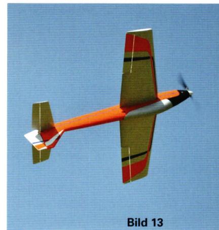
foil iron set to ~150 °C (the temperature on the outside of the felt pad is lower), lightly adhere it—do not stretch it yet—then remove the felt pad, lower the iron’s temperature to ~120 °C, and stretch the film to permanently adhere it. Iron temperatures above 120 °C applied directly to the shell’s surface should be avoided, as the thin fiberglass laminate tends to bubble otherwise! The final result is a model weighing 1140 g (ready to fly, including battery), which flies very well after break-in and adjustment (Figure 13).
3) *Modell flugsport*, May 2000, p. 35 ff.
*Bernhard Schönberger, MFG Falknis*


What's New at Leomotion.com

PRIDE AND GOOD IDEAS
 Markus Nussbaumer

News from HEBU

TEAM MANAGER "THIS" BOSSHARD
 Rodito Nussbaumer

34th HAHNENMOOS ALPINE MODEL AIRPLANE CAMP
Res Dauwalder
CORSAIR F4U – A WARBIRD WITH A MEMORABLE LOOK
Jürgen Rosenberger, Jürgen Prinz
SUMMER FUN 2026 AT MG USTER
Martin Wunderli
F3A EUROPEAN CHAMPIONSHIPS IN ST-MACAIRE, FRANCE
 Matthias Bosshard

52. 2026 ALPS CUP
 Emil Giezendanner

TWIN TOWN PARTNERSHIP
Wolfgang Voeller
EURO CONTEST GLIDER ACRO TOUR AUSTRIA 2026

BY YOUTH, FOR YOUTH
Lorena Betschen
ATOM, THE NEW DOUBLE-DECKER FROM CPLR
Matthias Bosshard
INSIGHTS INTO THE HISTORY OF SEAPLANES

YOU KNOW WHAT I MEAN? 125 YEARS OF THE SWISS AERO CLUB
Emil Giezendanner
SMALL, MODEL-LIKE SAILBOATS
Res Dauwalder
TRY-OUT DAY AT MFV WETTINGEN
Urs Keller
WELCOME, NEW MEMBER!
Andrea Bolliger
HORIZON HOBBY/LEMACO NEWS: MICRO OV-10 BRONCO 645 MM BY E-FLITE

FREE FLIGHT IN THE MIDDLE OF SUMMER
Urs Muntwyler
THE PC-21 STORY
Emil Giezendanner
COUPE DES ALPES – OBSERVE AND LEARN
Rodito Nussbaumer
NEWS FROM HEBU
 Julia Bucher

FROM 0 TO 100
Markus Nussbaumer
NOS REGION – A HUB FOR ELECTRIC AVIATION
Emil Giezendanner
MEMORIES
Wolfgang Völler
Have you almost forgotten about aircraft that take off and land vertically?
Emil Giezendanner
70 YEARS OF THE NIDWALDEN MODEL AIRPLANE CLUB
Martin Barmettler